When designing the power section of any circuit board, the most commonly used regulators are the 78XX, 79XX, LM317, LM337, or similar devices. Engineers know these controllers are reliable and easy to use, but their output current is limited. For higher currents, ADI's LT1083 regulator provides a simple and affordable solution.
A capable regulator
The LT1083 regulator (see symbol and pinout in Figure 1) supports an adjustable positive output voltage and can provide up to 7.5 A efficiently. The internal design allows operation with a voltage drop of up to 1 V between input and output. Under maximum output current conditions, the maximum drop is 1.5 V. A 10 uF output capacitor is required. Key features include:
- Adjustable output voltage
- Up to 7.5 A output current
- TO-220 package
- Internal power limiting
- Maximum differential voltage of 30 V
The LT1083 can be used in applications such as switching regulator front ends, constant-current supplies, high-efficiency linear regulators, and battery chargers. The version discussed here has an adjustable, configurable output. There are also fixed-output variants, such as LT1083-5 and LT1083-12, which provide fixed 5 V and 12 V outputs respectively.
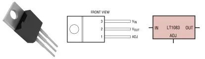
Figure 1: LT1083 regulator
Minimum application for a 5 V output
Figure 2 shows a reference application for a 5 V regulator. The input voltage must always be greater than 6.5 V. The supply voltage should not be excessively high because any extra voltage is dissipated as heat, reducing overall system efficiency. The regulator connects through its three pins to input, output, and an external resistor divider that sets the output voltage. It is strongly recommended to use two capacitors, one at the input and one at the output. This configuration sets the output to exactly 5 V. Therefore, the divider consists of two 1% precision resistors: 121 Ω and 365 Ω. Replacing these two passive components with an adjustable regulator or potentiometer yields a variable output power supply.
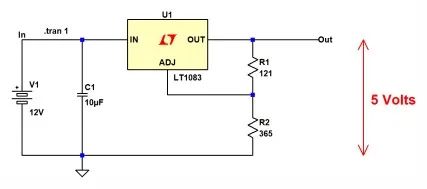
Figure 2: Minimal but fully functional application for a 5 V output
Figure 3 shows initial measurements of load current and integrated regulator power dissipation. Simulations were performed by testing different load values with load resistance from 1 Ω to 20 Ω. An important observation is that the output voltage remains very stable at 5 V even with large load variations. However, the current through the load and the regulator power dissipation vary significantly. As long as operation stays within the manufacturer's specified limits, the regulator is stable and safe.
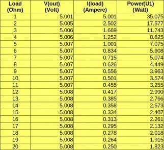
Figure 3: Measured results for the 5 V regulator schematic
The regulator is specified to support up to a 1 V drop between input and output. This drop is independent of load current; because it is small, system efficiency can be high. Figure 4 shows traces of input voltage (0 V to 8 V, red) and output voltage (blue). According to the manufacturer's characteristics, there is an effective "dropout" of about 1 V between these two voltages.
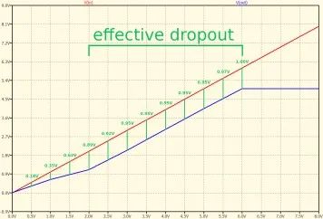
Figure 4: Traces of input, output, and dropout
Even with loads of different characteristics, the regulator's output voltage (determined by the resistor divider) remains highly stable, as shown in the traces in Figure 5.
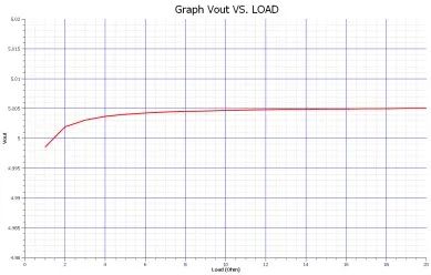
Figure 5: Curves showing output stability independent of load
Efficiency is much higher when the input voltage is close to the desired output voltage. Average efficiencies measured with various load values at three supply voltages were:
- Input 18 V: circuit efficiency = 26.71%
- Input 12 V: circuit efficiency = 40.84%
- Input 6.5 V: circuit efficiency = 75.37%
Thus, when the input voltage is significantly higher than the output voltage, the regulator must dissipate more power as heat.
Temperature effects
The regulator discussed here remains stable despite temperature variations. Although the manufacturer specifies stability of 0.5% in official documentation, actual results are better. Consider a simple application with the following static conditions equivalent to the previous example:
- Input voltage: 6.5 V
- Output voltage: 5 V
- Load resistance: 5 Ω (resistive)
- Load current: 1 A
- Regulator power dissipation: 1.51 W
Running a simulation while varying temperature from -10 °C to +100 °C shows that over this wide 110 °C range the output remains essentially constant. The integrated circuit is very stable; the maximum output variation between the two temperature extremes is only 6.2 uV.
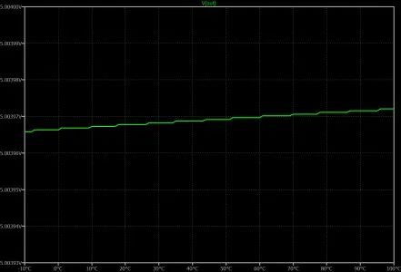
Figure 6: Output voltage variation across different operating temperatures
Protection diodes
The LT1083 generally does not require external protection diodes, as shown in Figure 7. The newer device design includes internal resistances that limit reverse currents. In addition, the internal diode between input and output can handle current spikes of 50 A to 100 A lasting a few microseconds. Therefore, a capacitor on the adjust pin is not strictly necessary. The regulator could be damaged only in an unlikely scenario where a capacitor larger than 5000 uF is connected to the output while the input pin is shorted to ground.
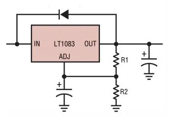
Figure 7: No external protection diode required between output and input
How to obtain different output voltages
There is a 1.25 V reference voltage between the output pin and the adjust pin. Placing a resistor between these two terminals produces a constant current through that resistor. A second resistor to ground sets the overall output voltage. A current of about 10 mA through R1 is adequate for precise regulation. Using an adjustable regulator or potentiometer allows creation of a variable voltage supply. The adjust pin current is very low, on the order of a few microamps, and can be neglected. For a 14 V output, the resistor calculations follow these steps:
- Input voltage Vin must be at least 1 V higher than the desired output, so Vin > 15 V
- There is always 1.25 V between output and reference pins
- R1 between output and reference pins should carry 10 mA
- R1 value equals the voltage across it divided by the required current
- The reference pin voltage equals the output voltage minus the fixed 1.25 V
- R2 also carries 10 mA and can be calculated with Ohm's law
With R1 = 125 Ω and R2 = 1275 Ω, the output equals 14 V. Replacing R2 with a 3.3 kΩ potentiometer yields a variable output from 1 V up to Vin.
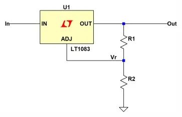
Figure 8: Resistor divider calculations for any desired output voltage

Figure 9: Equations used to calculate the two resistors
Conclusion
The three-pin LT1083 regulator is adjustable and easy to use. It includes many protection features typically found only in higher-end regulators. These protections handle short circuits and trigger thermal shutdown above 165 °C. Good stability supports the creation of high-quality power supplies. For full stability, use a 150 uF electrolytic output capacitor or a 22 uF tantalum output capacitor.