Introduction
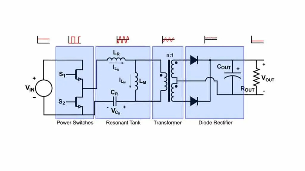
IR21814-type driver chips directly drive MOSFETs. The circuit offers simple drive, low cost, and small PCB area, and is used in many products. For the LLC resonant topology used here, the drive frequency varies between 195 kHz and 360 kHz. As frequency increases, losses in the driver rise according to Ploss = Qg * V * fs, and measurements showed the IR21814 junction temperature exceeded its limit at room temperature. The final solution was to use IR21814 plus a push-pull stage to share the drive current.
Circuit Operation
The circuit operation can be divided into the following stages:
(1) MOSFET lower device conducting, bootstrap capacitor charging
When DC PWMB input is high, the push-pull output DCDRVB goes high and drives Q121 on. DCPWMA is low, so the push-pull output DCDRVA is low and the high-side device Q120 is off. The bootstrap capacitor C308 is charged through the lower device Q121 up to VCC_FAN.
(2) Lower MOSFET off, bootstrap capacitor charged
After the lower device turns off, the bootstrap capacitor voltage floats. The floating voltage is equal to VCC_FAN and serves as the supply for driving the high-side device Q120.
(3) Lower MOSFET off, upper MOSFET conducting
When DCPWMA input goes high, the push-pull output DCDVRA goes high and drives Q120 on.
(4) Upper MOSFET off, lower MOSFET conducting
Driver Chip Selection
Comparison of several driver chips:
| Parameter | MIC4424B | IXDN404SI | LM5110 | NCP5181 | IR2181(4) | IR2110 |
| tr max (ns) | 35 | 18 | 25 | 60 | 60 | 35 |
| tf max (ns) | 35 | 17 | 25 | 40 | 35 | 25 |
| ton delay max (ns) | 75 | 40 | 40 | 170 | 270 | 150 |
| toff delay max (ns) | 75 | 39 | 40 | 170 | 330 | 125 |
| Isource (A) | 3 | 4 | 3 | 1.4 | 1.9 | 2.5 |
| Isink (A) | - | - | 5 | 2.2 | 2.3 | 2.5 |
From the above switching-loss performance comparison, IR2110 has fast switching speed and large Isink/Isource, resulting in lower losses. However, IR2110 is available in a relatively large package (WSOP16) and is more expensive, so it was not chosen. Other listed chips lack bootstrap capability and are therefore not suitable.
IR21814 is mature and widely used. Given its performance and availability, IR21814 was selected as the PWM driver, with an added push-pull stage to share the drive current.
5.4.2 Push-Pull Transistor Selection
With supply voltage VCC_FAN = 14.5 V and considering voltage ripple, the chosen transistors must have Vce or Vceo rating greater than 20 V. The forward drive resistance is R = 10 ohm + 2.55 ohm = 12.55 ohm, so the forward peak drive current I = 14.5 V / 12.55 ohm = 1.16 A. The reverse drive resistance is R = 2.55 ohm, so the reverse peak drive current I = 14.5 V / 2.55 ohm = 5.7 A. Therefore, transistor peak current rating must exceed 5.7 A.