01. Principle of the LLC Circuit
The LLC circuit is a resonant network composed of two inductances and one capacitor, hence the name LLC. Its topology can be implemented in half-bridge or full-bridge configurations depending on the MOSFET arrangement. The two inductances represent the transformer primary leakage inductance (Lr) and the magnetizing inductance (Lm), and the capacitor is the transformer primary resonant capacitor (Cr). The LLC topology enables soft switching for the MOSFETs via resonance, reducing switching losses. Conduction losses of the MOSFETs are also relatively low, which reduces heat generation and may eliminate the need for additional heatsinking. For these reasons, LLC circuits are widely used in DC/DC converters.
02. Advantages of the LLC Circuit
LLC converters offer low cost, high reliability, and good EMI performance. In typical switching designs, the LLC stage is often used together with a PFC stage to reduce the required capacitance of high-voltage filtering capacitors, decrease component count and product size, and increase power density.
03. Disadvantages of the LLC Circuit
LLC converters achieve high efficiency only near the resonant frequency, so they are not ideal for wide input-voltage ranges and are commonly used after a PFC stage. They normally operate near resonance and may switch to a wider input operating mode only when the input is turned off to obtain longer hold-up time. Because the circuit uses a bridge structure, the MOSFET drain-source voltage (VDS) is limited by the supply voltage. If the circuit becomes detuned, through currents can flow in the MOSFETs and switching losses increase.
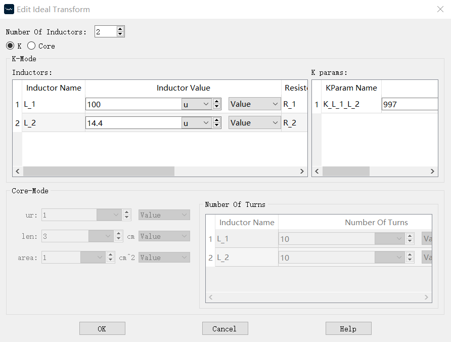
04. LLC Circuit Setup
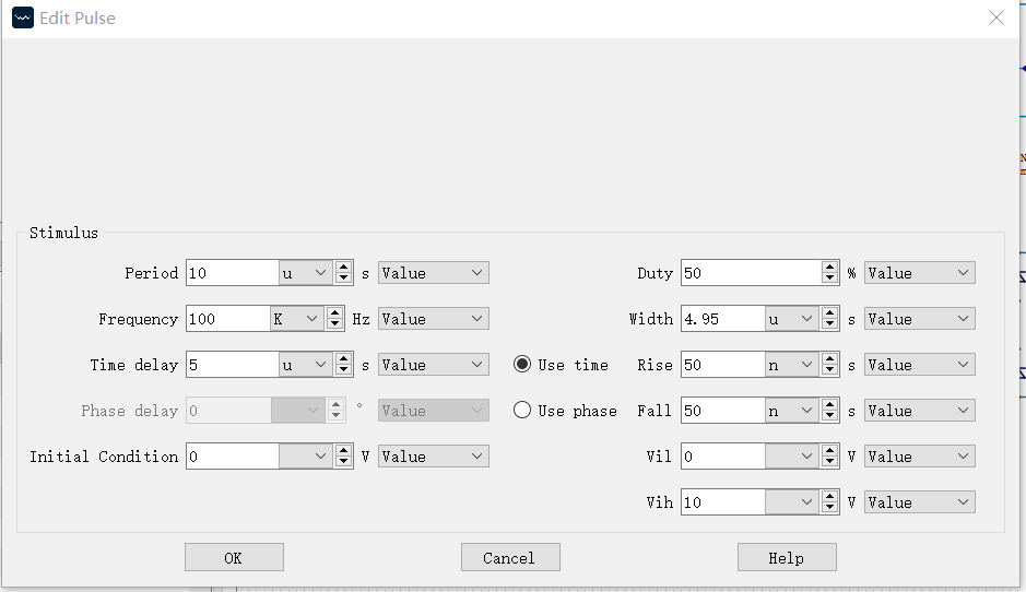
Pulse source settings, transformer settings, and other parameters:
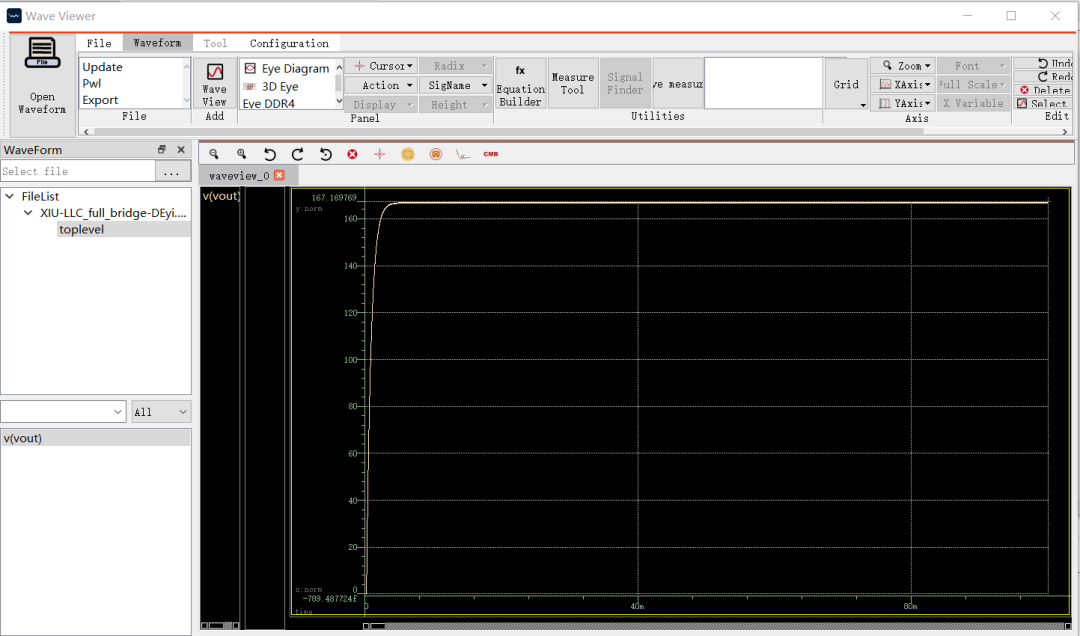
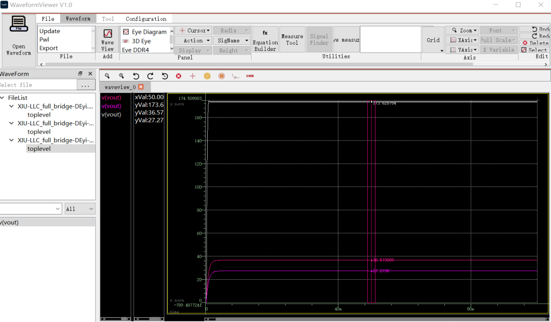
05. Results
Input 400 V, output 167 V, meeting AC-DC step-down requirements.
PULSE frequency = 100 kHz / 150 kHz / 250 kHz
VOUT = 173 V / 36 V / 27 V
The operating sequence of the LLC during one switching cycle is not described in detail here. PowerExpert simulation software can be used to observe and debug the operating modes of the relevant stages.