1. Nature of Power-line Conducted Emissions Testing
The conducted emissions test on the power line measures the current flowing through the LISN resistor. That current includes both differential-mode current and common-mode current.
differential-mode interference equivalent model and equivalent calculation
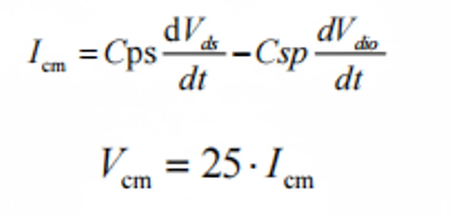
common-mode interference equivalent model and equivalent calculation
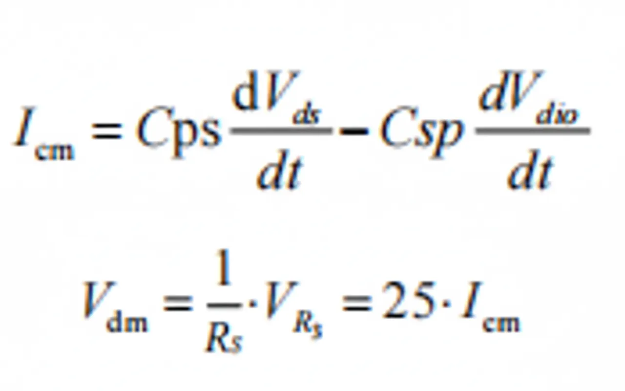
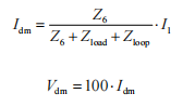
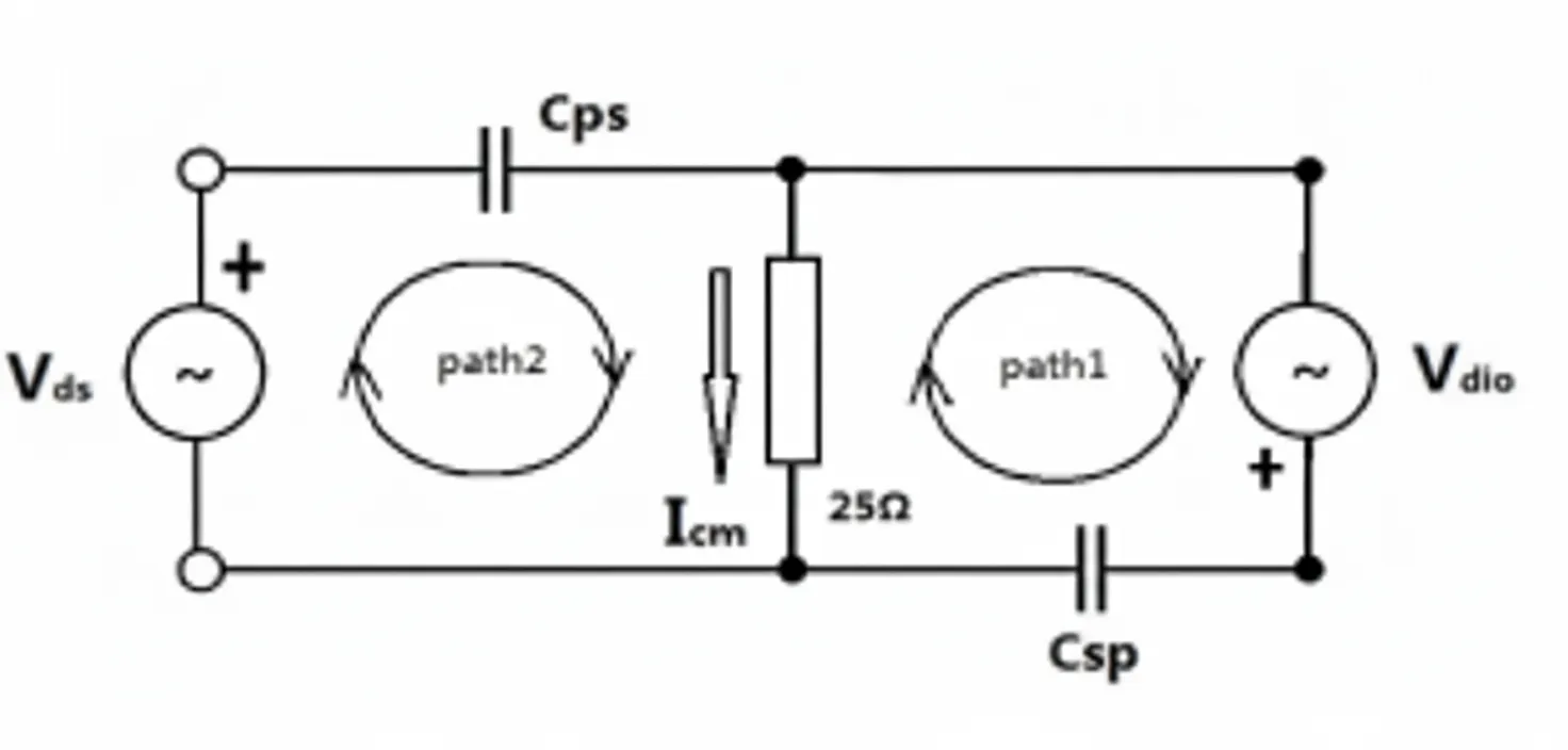
non-intrinsic differential-mode interference equivalent calculation (common-mode to differential-mode conversion)
2. Approaches to Reduce Power-line Conducted Emissions
Given the test principle above, the primary objective is to reduce the current flowing through the LISN resistor (both differential-mode and common-mode currents). Common solutions are:
- Add an AC input filter to attenuate currents reaching the LISN. Filters address both differential-mode and common-mode interference.
- Reduce noise current at the source and reduce coupling along propagation paths.
3. Localization Methods for Power-line Conducted Emissions
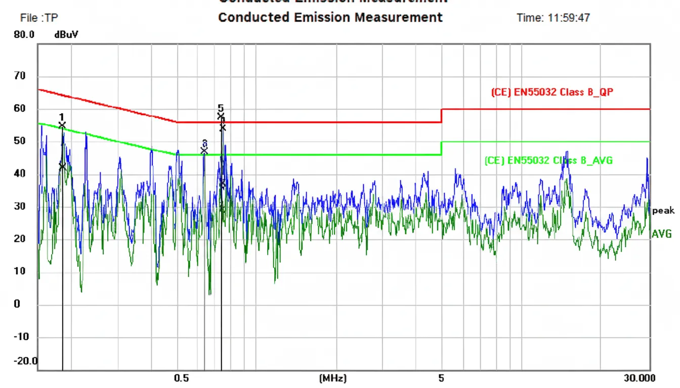
Uninformed trial-and-error fixes are inefficient and often ineffective. Localization should follow the test principle and the coupling mechanisms of the interference. Use test data features to guide analysis: identify whether offending frequency points have harmonic relationships, whether they align with a switching power supply fundamental frequency and its harmonics, and whether the interference appears as discrete spikes or broadband noise.
Multiple harmonically related peaks
Multiple discrete peaks that are harmonically related typically indicate switching-frequency noise and its harmonics. If the rest of the low-frequency band meets margins, the noise may be bypassing the AC input filter via spatial coupling or being induced in filter components and entering the LISN.
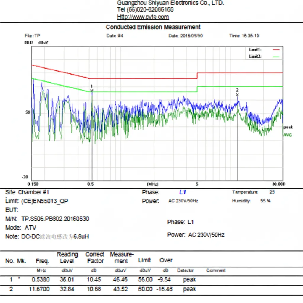
Multiple non-harmonically related elevated frequencies
Multiple peaks without harmonic relationships, with the entire low-frequency band elevated, often indicate that the AC input filter is being bypassed by near-field coupling or that the filter is resonating (commonly an LC series resonance), reducing insertion loss and allowing noise into the LISN.
Single resonant or broadband peak
A single frequency or a single-frequency broadband noise exceeding limits, while other frequencies remain within margins, usually indicates a source resonance frequency and insufficient insertion loss of the AC input filter. The resonant noise is not sufficiently attenuated and is detected by the LISN.
Single spike
A single discrete spike exceeding limits, with other frequencies within margins, typically indicates switching-frequency noise coupling through space to components on the AC input filter, inducing noise that bypasses filter attenuation and is detected by the LISN.
Use of spectrum analyzer and oscilloscope for localization
An oscilloscope is a common engineering tool for waveform inspection; a spectrum analyzer is used for EMC troubleshooting. Combined, they accelerate localization. Use a spectrum analyzer with a sniffer probe to locate the general area of the interference and a pointed probe to find the exact source. For high-voltage sections of switching power supplies where the spectrum analyzer probe cannot be used, use an oscilloscope to measure voltage and current waveforms at key nodes to aid localization.
Note: Do not use a spectrum analyzer pointed probe to directly measure noise sources with voltages ≥48 V. When measuring primary-side waveforms of switching power supplies with an oscilloscope, power the oscilloscope with a two-conductor cord (no protective earth), otherwise a mains earth short can damage equipment.
Use of ferrite cores or common-mode chokes for diagnostic aiding
Ferrite cores and common-mode chokes can assist in locating power-line conducted problems.
Ferrite core method: Place a ferrite core around the AC input conductors and add turns as needed to observe the effect on filter insertion loss. The number of turns depends on the filter band and ferrite material.
Common-mode choke method: For cases where the entire band is elevated and it is unclear whether the input filter is bypassed by spatial coupling or if the filter is resonant, add a common-mode choke (similar to the PCB filter choke) or temporarily short the onboard common-mode choke to assist analysis.
4. Analysis and Tuning Strategies
Magnetic component spatial coupling and mitigation
Physics indicates that a current-carrying conductor generates a magnetic field with closed field lines. According to Faraday's law, magnetic flux through a closed loop induces an electromotive force and induced current. The magnitude of radiated magnetic field from a current-carrying conductor depends on current amplitude, distance, and frequency. Increasing distance is an effective way to reduce coupling for given current and frequency. Magnetic component field radiation is a common cause of power-line conducted emissions; primary mitigation strategies include:
- Use magnetically shielded components (magnetic-shielded inductors).
- Use components with low leakage flux, such as toroidal inductors or toroidal cores.
- Increase distance between radiating magnetic components and sensitive circuits or components.
- Reduce the di/dt of radiating components.
- Reduce mutual coupling between magnetic components by increasing separation or changing relative orientation of their fields.
- Change winding arrangements of magnetic components to reduce field coupling.
E-core non-shielded inductors are widely used in buck, boost, and power amplifier output LC filters because of low cost. However, their low-frequency magnetic radiation can couple into the input stage of switching power supplies and cause conducted emissions failures. During PCB design, maintain strict separation between such inductors and the input stage. If spacing cannot be achieved, prefer magnetic-shielded inductors or toroidal inductors.