Motor starting
Low line voltage reduces the available starting torque of three-phase and single-phase motors, for example pumps, water coolers, window and rooftop air-conditioning compressors, and many other applications. Buck-boost transformers can be used to raise the line voltage to the nominal level.
Series secondaries
Given a source that sags to 185 V at peak load and a 120×240 V to 16×32 V buck-boost transformer, the 120 V coils can be placed in parallel on the line side while the 16 V coils are connected in series. This results in each coil seeing 107 V and each secondary coil producing 14 V (see Figure 1). The two secondary coils in series provide 28 V of boost, raising the line-to-line voltage from 185 V to 213 V. That yields approximately 123 V from phase to neutral, which is very close to the nominal 120 V.
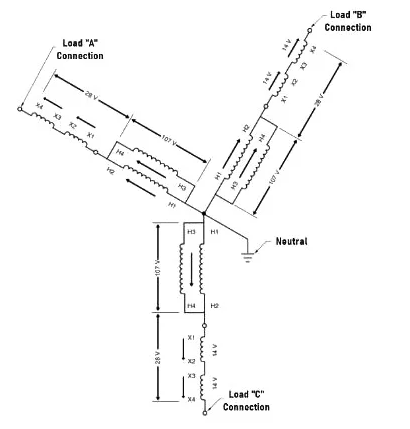
Figure 1. Buck or boost when secondaries are in series
Notes
The buck-boost transformer ships wired as an isolation transformer. After installation, the primary and secondary can be reconnected as an autotransformer to create a buck-boost connection.
During off-peak periods the input to the buck-boost transformer can rise to 208 V. The amount of boost rises proportionally with the increased primary voltage. Each primary coil would see 120 V and each secondary coil would output 16 V. With the secondary coils in series the line-to-line voltage would be 240 V and the line-to-neutral voltage about 138.6 V. That value may be too high and could cause problems for equipment designed for 120 V.
Parallel secondaries
Starting from the same 185 V peak-load sag and a 120×240 V to 16×32 V buck-boost transformer, the 120 V coils can be placed in parallel on the line and the 16 V coils can be paralleled on the secondary. This yields about 107.3 V on each coil and about 14.3 V output on each secondary coil (see Figure 2). The two secondary coils in parallel provide 14.3 V of boost, raising the line-to-line voltage from 185 V to 199.3 V. That gives about 115.06 V from phase to neutral, which is close to the nominal 120 V.
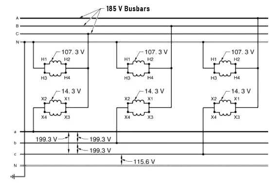
Figure 2. Buck or boost when secondaries are in parallel
During off-peak periods the input can rise to 208 V and the boost increases proportionally. Each primary coil would see 120 V and each secondary coil would output 16 V. With the secondary coils paralleled the line voltage would be 224 V and the line-to-neutral voltage about 129.3 V.
Users can choose series or parallel secondary wiring as required. Changing between the two is accomplished simply by reconnection of the secondary leads.
Raising 208 V to 230 V
Some applications use a 208Y/120 V system but require a 230 V supply, for example a 230 V motor or a 230 V air-conditioning unit fed from a 208 V line. The required boost can be achieved by placing the buck-boost transformer primary and secondary coils in series. Each series primary coil would see about 104 V. With a turns ratio of 7.5:1 the secondary coil voltage is about 13.9 V per coil. This provides 27.8 V of boost, giving a line-to-line voltage slightly under 236 V.
Parts heater example
A small industrial facility with 208Y/120 V service uses small cabinets to heat parts. The facility is concerned that longer heat-up times slow production.
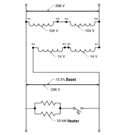
Figure 3. Voltage can be raised from 208 V to 236 V to supply 230 V parts heaters
AC voltages in power systems should be within -10% and +5% of the rated voltage.
The cabinet has two 5 kW, 230 V heating elements, which provide 10 kW at 230 V. With only 208 V available, the voltage is 90% of the 230 V nominal, so the power is about 81% of nominal, approximately 8.1 kW. The heaters require roughly a 10% voltage increase to operate at their nominal load. The wiring configuration described above raises the voltage from 208 V to just under 236 V, a 13.3% increase. That is within the voltage tolerance of most loads, so this is an appropriate application for a buck-boost transformer.
Extruder heaters
A manufacturing plant with 208 V three-phase power uses extruders that require 230 V heating elements. Material is forced through a barrel by a large screw; band heaters around the barrel provide heat to melt the plastic pellets so the material can be formed through a die. Different plastics and colors require different heat settings.
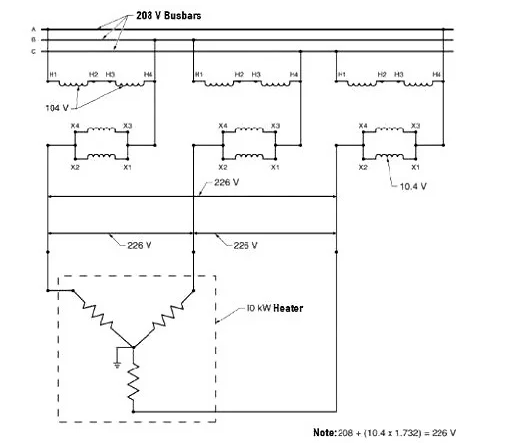
Figure 4. Voltage can be raised from 208 V to 226 V to supply 230 V extruder band heaters
A 10 kW 230 V band heater at 208 V supplies about 8.1 kW instead of the designed 10 kW. An extruder may have eight band heaters, so the system would supply about 65 kW rather than the required 80 kW.
The extruder load was calculated from nameplate circuit data. The total load current is 227 A. A 10% boost is sufficient to raise the extruder heaters powered from 208 V toward 230 V. A buck-boost transformer with a winding ratio of 10:1 can provide that boost. Primaries would be sized 120×240 V and secondaries 12×24 V. The per-phase buck-boost transformer size is calculated as:
P = (I × E) / 1000 = (227 × 24) / 1000 = 5.448 kVA
The actual voltage rise is about 18 V (10.4 × 1.732 ≈ 18). Therefore the plant could install three 5 kVA buck-boost transformers to raise the extruder heater voltage to about 226 V (208 + 18 = 226). Larger buck-boost transformers could better reduce heat-up issues, but they may reduce power factor.