BJT constant-current circuit
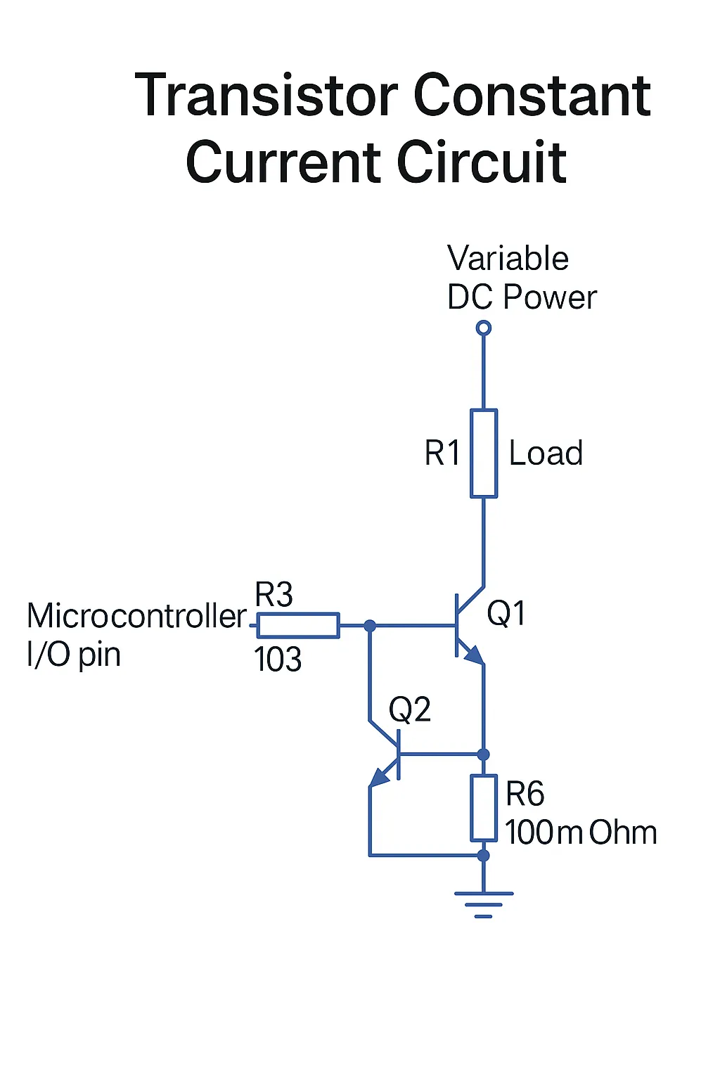
The BJT-based constant-current circuit uses the base-emitter forward voltage of Q2, typically about 0.6–0.7 V. When Q2 conducts, it pulls Q1's base low and Q1 turns off, so the load R1 is not driven by Q1. The current through R1 equals the current through R6, neglecting the base currents of Q1 and Q2. The current through R6 is determined by the voltage across it (about 0.6–0.7 V) divided by R6, so the current through R1 remains essentially constant. This keeps the load current steady even if the supply voltage VCC varies.
Op amp constant-current circuit
The op amp solution exploits the voltage-following property of the amplifier, where the two inputs (Pin3 and Pin2) are held at the same voltage. When a stable input voltage Vin is applied via R4, the voltage across R7 is also Vin, so the current through R7 is fixed. As with the BJT design, the load current through R2 equals the current through R7, so R2 sees a constant current even if its supply voltage changes.
Zener diode constant-current circuit
In the zener-diode-based design, the base of transistor Q4 is clamped to the zener voltage Uzd. The voltage across R10 is therefore U = Uzd - 0.7 V, which remains constant. As a result, the current through R10 is fixed even if the VCC supply varies, and the current through the load R8 remains constant, achieving a constant-current effect.