Overview
Voltage-to-current (V/I) conversion transforms an input voltage signal into a current signal that follows a defined relationship. The converted current functions as an adjustable constant-current output, and the output current should remain stable and not vary with changes in load. V/I converter circuits typically use negative feedback, implemented as either series or shunt current feedback, and are commonly applied in industrial control and many sensor applications.
Common voltage-to-current circuits
1. Basic op amp plus transistor constant-current circuit
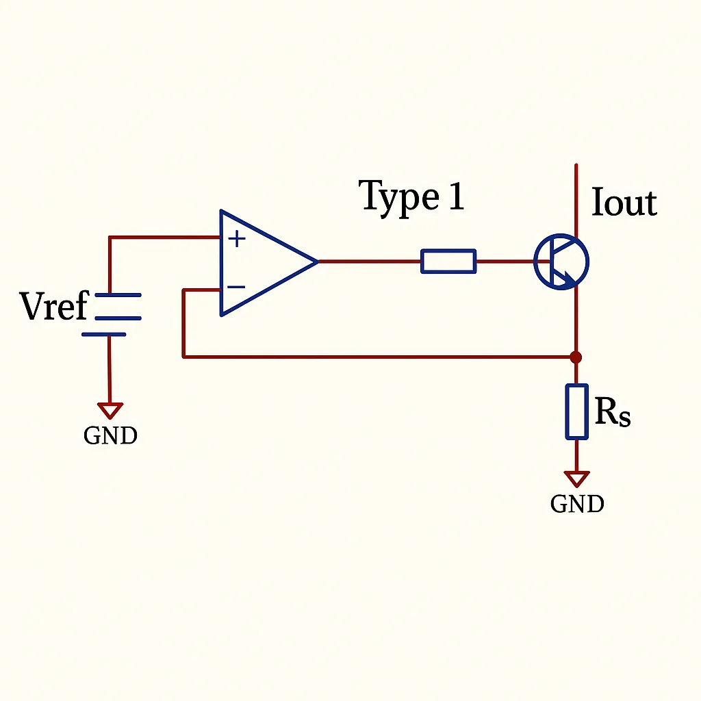
Circuit structure: This commonly used voltage-to-current converter is effectively a constant-current source. It consists of an operational amplifier, a transistor (BJT or MOSFET), and several resistors. The output current is given by Iout = Vref / Rs.
Simulation analysis
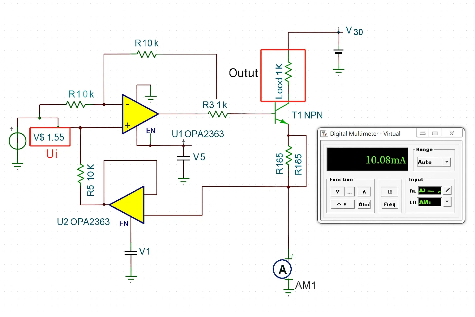
Simulation was performed using the circuit above. The op amp used was OPA2363 with a 2.5 V reference supply. Rs was set as a precision resistor, and a 250 ohm resistor was used as the load. The simulated output current is 9.9 mA, which is close to the theoretical value of 2.5 V / 250 ohm = 10 mA.
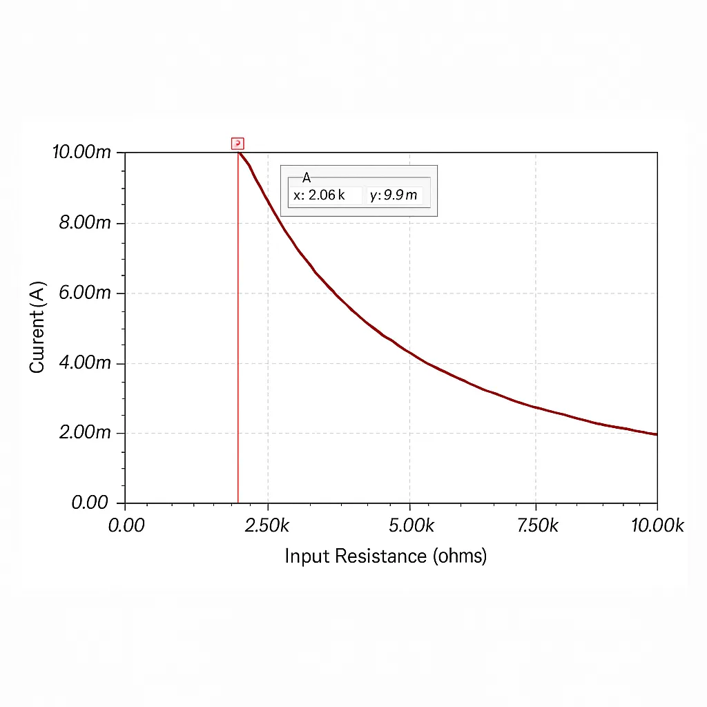
A DC parameter sweep was used to evaluate load driving capability at 10 mA. At 10 mA, the circuit can drive a maximum load of about 2.06 kohm.
2. Alternative feedback topology
Circuit structure: This topology is commonly presented in textbooks and is somewhat more complex. Its output current is I = Ui / R3.
In practice, this topology is less often used directly; variants of the simpler circuit above are preferred. In the example below, the output current is 1.65 V / 165 ohm = 10 mA.
Load-driving capability for this circuit at 10 mA was measured; the maximum load is about 3.55 kohm.
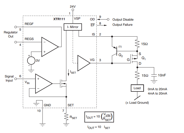
Integrated voltage-to-current converter
Integrated devices simplify implementation of precision V/I conversion. For example, the XTR111 is a precision voltage-to-current converter; the datasheet includes the following reference circuit.