Question
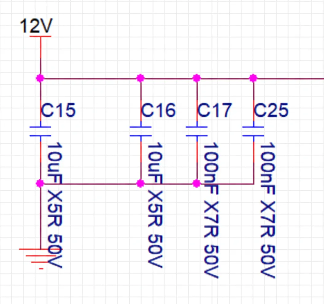
On a power supply, placing 10uF and 0.1uF in parallel is exactly a 100x ratio. Why not use 1uF and 0.1uF instead?
Background
This is a fairly niche question and is unlikely to appear in many interviews, but it is frequently encountered in practical designs.
Hidden effect
At first glance this seems like an obscure point, but it does reflect a subtle behavior of parallel capacitor combinations that is worth understanding.
Online discussions offer several explanations: filter bandwidth, the high- and low-frequency characteristics of capacitors, and characteristic impedance arguments. All are valid perspectives.
Here we focus on a different dimension: resonance and anti-resonance points.
Simulation verification
To make the verification more persuasive, we used Murata's online simulation tool SimSurfing.
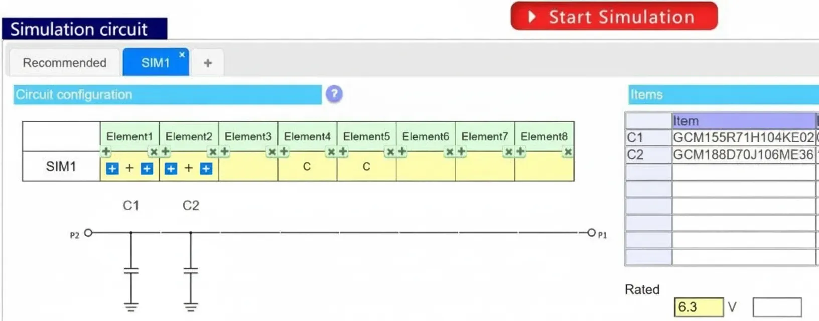
Step 1: 0.1uF + 10uF
First, build a simple filter: 0.1uF in parallel with 10uF.
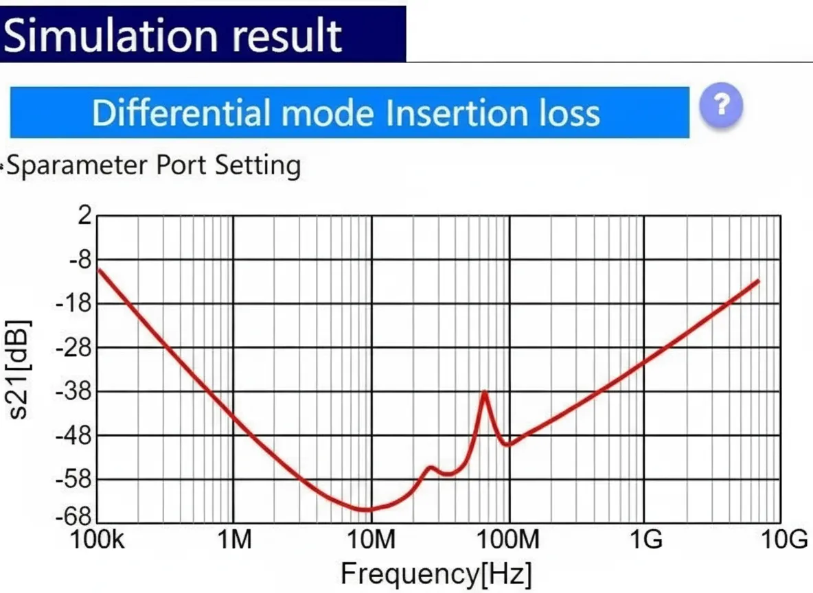
Look at the S21 (insertion loss) curve for this filter, shown below.
If you read the previous article, this waveform should look familiar. Why does the curve have this shape? Below we focus on the resonance and anti-resonance points, as shown.
Resonance point: each capacitor has its own self-resonant frequency.
Why does anti-resonance occur?
When the signal frequency lies between the self-resonant frequencies of the two capacitors, one capacitor behaves inductively while the other behaves capacitively. A parallel combination of an inductive element and a capacitive element forms an LC parallel resonant circuit. That LC circuit resonates at a specific frequency, producing an anti-resonance point.
Understanding this mechanism explains why the anti-resonance point appears.
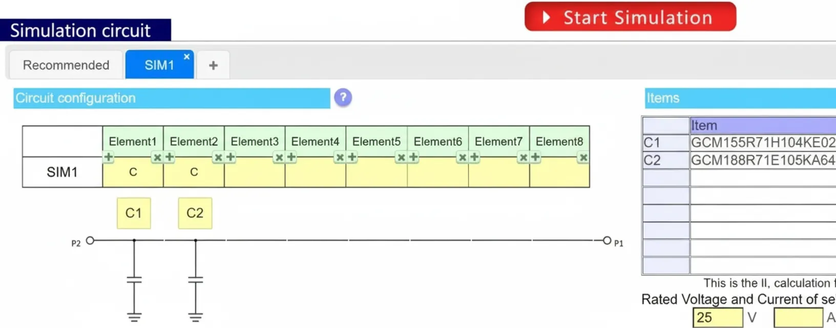
Step 2: 0.1uF + 1uF
Next, consider a filter using 0.1uF in parallel with 1uF.
Now look at the S21 curve for this filter.
Compared with the 10uF + 0.1uF case, the differences are clear:
- The resonance and anti-resonance points are closer together.
- The absolute S21 values are generally lower.
Analysis
Looking beyond the surface:
- The clustering of resonance and anti-resonance points indicates that the effective filtering bandwidth of the 1uF + 0.1uF combination is narrower than that of the 10uF + 0.1uF combination. A narrower effective bandwidth is not usually desirable for decoupling across a wide frequency range.
- Based on impedance mismatch principles for filters, within the effective filtering band a larger S21 magnitude corresponds to better attenuation. Therefore, the 10uF + 0.1uF combination provides better overall filtering performance than the 1uF + 0.1uF combination in this example.
Conclusion
This discussion is simple and covers a small but important point: using widely spaced capacitance values, such as a 100x ratio, helps spread self-resonant frequencies and avoids clustered resonance and anti-resonance behavior, which improves effective filtering across a wider frequency range.