Overview
In devices such as laptop computers, tablets, smartphones, televisions, and automotive electronics, users sometimes hear a high-pitched or "chirping" noise. This phenomenon, commonly called squeal, can originate from passive components such as capacitors or inductors. The mechanisms for capacitors and inductors differ; in particular, power inductors in DC-DC converters have multiple, sometimes complex causes for audible noise. This article explains the main causes of squeal in power inductors used in DC-DC converters and summarizes effective countermeasures.
Causes of Squeal in Power Inductors
1. Intermittent operation, variable-frequency modes, and load modulation can produce audible-frequency excitation
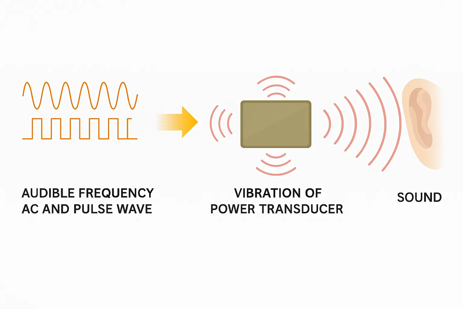
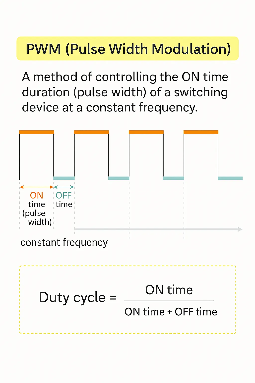
Sound is a mechanical wave in air; human hearing typically responds to roughly 20 Hz to 20 kHz. When alternating currents or pulsed currents within the audible band flow through a power inductor, the inductor body can vibrate and emit audible coil noise. DC-DC converters use switching to produce pulsed currents. By varying the on-time (pulse width), a stable DC output is obtained. This pulse-width modulation (PWM) switching is widely used in DC-DC converters.
Although switching frequencies are often hundreds of kHz to MHz and therefore above the audible range, audible noise can still occur. Common causes include operating the converter intermittently to save battery, or switching between PWM and pulse-frequency modulation (PFM), where the converter runs in a variable-frequency mode. Figures 1 and 2 illustrate the basic concepts and the PWM vs. PFM modes.
2. PWM dimming and other intermittent-drive schemes
To save power, some devices use intermittent operation for functions like LCD backlight auto-dimming. One common method is LED PWM dimming, which controls LED on-time and off-time to set average brightness while minimizing color shifts. PWM dimming typically uses a relatively low repetition rate around 200 Hz. While 200 Hz is not noticeable visually as flicker, it lies well within the audible range. If a power inductor on the board carries the intermittent current associated with PWM dimming, the inductor can vibrate at that audible frequency and produce squeal.
Note: Duty cycle is the ratio of ON time to the total switching period (ON time + OFF time). For LED PWM dimming, brightness corresponds to ON time / (ON time + OFF time).
3. Variable-frequency DC-DC operation (PFM)
PWM converters are efficient at moderate and heavy loads (typically 80% to 90%+), but efficiency drops at light loads because switching losses are proportional to frequency. To improve light-load efficiency, many converters automatically switch from PWM to PFM. In PFM the ON time is fixed while the OFF time is extended as load decreases, reducing switching frequency. The reduced frequency can fall into the audible range (around 20 Hz to 20 kHz), causing the power inductor to emit audible noise.
4. Load-induced periodic currents
Other system-level periodic current patterns can excite audible vibration. For example, CPUs in portable devices may periodically change current consumption for power management. If this periodicity falls in the audible band, nearby power inductors may vibrate and squeal.
Role of the Power Inductor in DC-DC Converters
An inductor allows DC current to pass while opposing changes in current via self-inductance. It stores energy as magnetic energy and releases it back to the circuit; the stored energy is proportional to the inductance. Power inductors (also called power coils or choke coils) are a key component in switching power supplies such as DC-DC converters. They smooth the high-frequency pulses produced by switching elements together with capacitors.
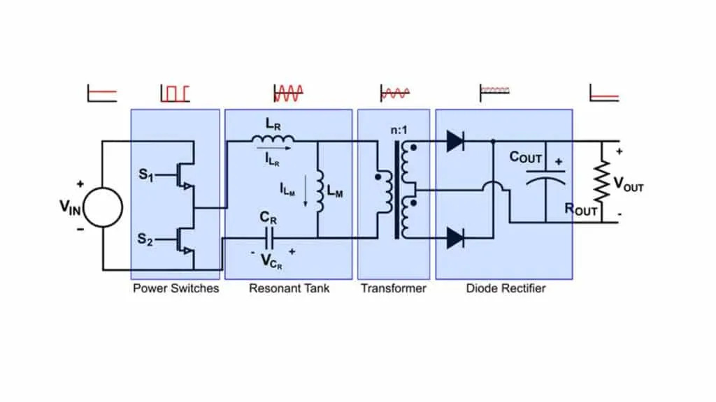
Because large currents flow in power inductors, wound types are common. High-permeability magnetic materials (ferrite or soft magnetic metal) are used in the core to achieve high inductance with few turns, enabling compact designs. Figure 3 shows a typical non-isolated buck DC-DC converter using a power inductor.
Vibration Mechanisms and Noise Amplification
When currents within the audible range flow through a power inductor, the resulting mechanical vibration can cause squeal. The main vibration mechanisms and noise-amplification paths include:
- Vibration mechanisms:
- Magnetostriction of the magnetic core
- Mutual attraction between magnetized core parts
- Leakage flux acting on the winding causing the winding to vibrate
- Noise-amplification mechanisms:
- Contact with nearby components
- Leakage flux exciting nearby magnetic parts
- Resonance with the overall assembly including the PCB
Magnetostriction of the core
Magnetostriction (magnetically induced strain) causes very small dimensional changes in a magnetic material when it is magnetized. In ferrite or other core materials, the alternating magnetic field produced by the winding can cause repeated expansion and contraction of the core. Although the absolute deformation is small (on the order of 10^-4 to 10^-6 of the original size), repeated magnetostriction can produce audible vibration when the core assembly is mounted on a PCB. If the inductor vibration frequency coincides with a structural resonance of the PCB or assembly, the vibration is amplified and becomes audible.
Mutual attraction between magnetized core parts
In fully shielded (closed magnetic circuit) power inductors that use a pot core and a shielding core, a small air gap may exist between the pot core and the shield. When the core parts are magnetized they can behave like magnets and attract each other. The attraction force across the gap can cause the assembly to vibrate at audible frequencies. Adhesive is typically used to seal the gap, but it is not rigid enough to fully suppress vibration because it must tolerate mechanical stress without cracking.
Leakage flux causing winding vibration
Open magnetic-path designs (unshielded inductors) do not have the pot-core/shield-core attraction issue, but leakage flux can act on the winding itself. The interaction of leakage flux and current in the winding produces forces (per the Lorentz force) that cause the winding to vibrate when driven by an alternating current, which can produce audible noise.
Noise amplification: contact, nearby magnetic parts, and assembly resonance
On high-density power boards, even small inductor vibrations can be amplified if the inductor contacts other components. Leakage flux can also magnetically excite nearby metal shields or magnetic components, causing them to vibrate. Finally, an inductor mounted on a PCB forms part of an assembly with multiple structural natural frequencies. If the excitation frequency matches one or more of these modes, vibration is amplified and audible squeal can occur.
Figure 8 shows finite-element method (FEM) modal analysis of a PCB with a centrally mounted power inductor. The model fixes the PCB along two long edges and identifies multiple natural modes. Notably, modes with significant Z-direction motion (height) can shift to much lower frequencies once the inductor is mounted on the board, increasing the chance of audible excitation.
Analysis model: power inductor mounted at the center of an FR-4 PCB. Boundary conditions: two long edges fixed.
Mode 1: ~2034 Hz
Mode 2: ~2262 Hz
Mode 5: ~4048 Hz
Mode 18: ~16226 Hz
Countermeasures for Power Inductor Squeal
The following countermeasures focus on reducing or eliminating audible noise from power inductors in DC-DC converters.
Key 1: Avoid currents in the audible band
Avoiding excitation within the human audible range is the fundamental mitigation method. Where intermittent operation or variable-frequency operation is required for power saving, additional measures below should be considered.
Key 2: Keep magnetic materials away from the inductor
Do not place magnetic shields or other magnetic materials near the inductor where they could be excited by leakage flux. If proximity is unavoidable, choose a shielded inductor with low leakage flux and pay attention to orientation to minimize coupling.
Key 3: Detune structural resonances
Changing the inductor shape, type, placement, or PCB fastening can shift the assembly natural frequencies and help avoid resonance with excitation sources. Smaller inductors (under about 5 mm) tend to have higher natural frequencies and are less likely to produce audible noise. Larger inductors (around 7 mm and above) are more prone to squeal.
Key 4: Replace with molded metal-integrated inductors
Replacing conventional unshielded or shielded wound inductors with metal-integrated molded inductors is an effective solution. These are formed by embedding a hollow coil into a soft magnetic metal powder and molding it into a single unit. Because there are no gaps between core parts, mutual attraction between separate cores is eliminated. The winding is bonded to the magnetic material, which suppresses vibration from leakage flux acting on the winding. Some molded metal inductors also use magnetic materials with lower magnetostriction, further reducing vibration. Replacing a shielded or unshielded wound inductor with a molded metal-integrated type can significantly reduce audible noise.
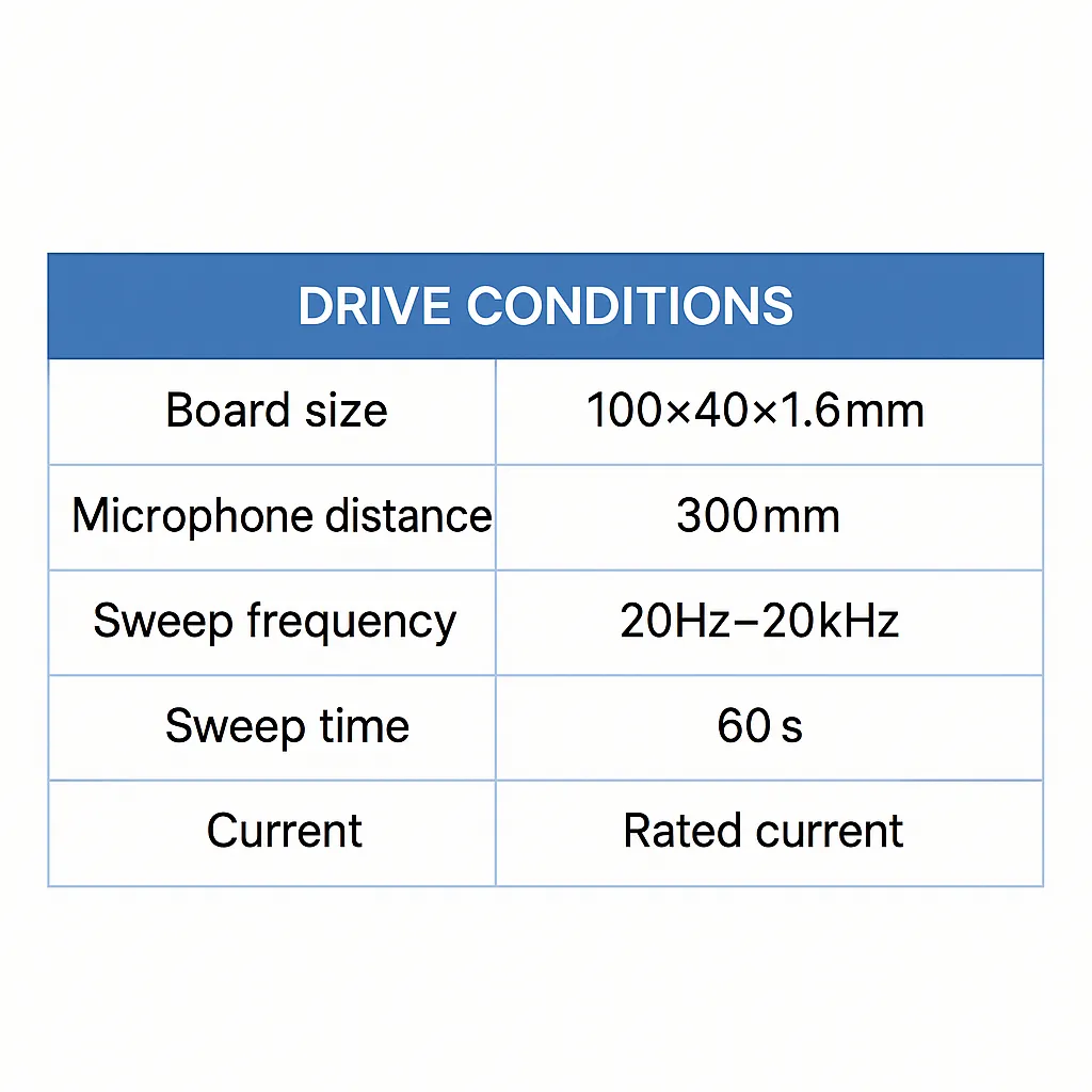
In comparative measurements, shielded vs. half-shielded inductors (approx. 6 mm) and shielded vs. metal-integrated molded inductors (approx. 12 mm) were tested. A microphone in an anechoic box recorded peak sound pressure while supplying a sinusoidal current from 0 A to rated current on a PCB-mounted sample for 60 seconds over 20 Hz to 20 kHz. Results showed that shielded inductors can produce 30 to 50 dB SPL across wide bands, whereas metal-integrated molded inductors produced noise at levels similar to the background noise across most bands, with peak suppression of roughly 20 dB compared with shielded wound types. A 20 dB reduction corresponds to a tenfold decrease in sound pressure, demonstrating the effectiveness of the molded metal-integrated approach.