Chapter 1: Alarm Subsystem
1.1 System Architecture
The alarm subsystem detects and reports unauthorized entry into protected areas and receives emergency alarm messages using various sensors and electronic information technologies. It consolidates and transmits those messages to the designated incident-receiving center, enabling rapid and accurate alarm receipt, verification, handling, and dispatch.
The alarm subsystem consists of front-end devices, alarm control panels and auxiliary equipment, transmission networks, and an integrated management platform. The overall system architecture is shown below:
1) Front end
Front-end alarm devices include various detection sensors and emergency alarm devices. They detect events and generate discrete alarm signals, which are then transmitted to the alarm control panel.
Detection sensors include dual-technology detectors, vibration detectors, infrared beam detectors, passive infrared detectors, glass-break detectors, panic buttons, smoke detectors, gas detectors, and other types of detectors.
Emergency alarm devices include single-button alarm posts, alarm boxes, and alarm panels that report alarms when the emergency button is pressed.
2) Alarm control panels and auxiliary equipment
Alarm control panels include bus-based network alarm panels, network alarm panels, and video alarm panels. They analyze loop voltage and arming status to determine alarms or faults, mark events, generate CID-format signals, and forward those signals to the integrated management platform.
Auxiliary equipment includes alarm keypads, relays, zone expansion modules, remote controls, printers, and similar devices.
3) Transmission network
The transmission network supports the system by uploading alarm signals collected by front-end detectors to the incident-receiving center. Common transmission network types are the public switched telephone network (PSTN), wireless networks (GPRS/3G/4G/WIFI), and Internet.
4) Integrated management platform
The alarm subsystem module within the integrated management platform handles alarm receipt and processing, device configuration and management, and alarm query and reporting. It can integrate and interoperate with video surveillance, video intercom, and unified access subsystems.
1.2 System Design
1.2.1 Front-end placement design
Placement of front-end alarm devices directly affects interior and exterior security. Unlike video surveillance, alarm devices provide early prevention so staff can be notified immediately and take appropriate action. Recommended placement of front-end alarm devices is summarized below.
Table 8: Recommended detector placement
| Alarm Location | Alarm Requirement |
|---|---|
| Perimeter | Protect against external intrusion such as climbing or crossing. Use infrared beam detectors or electronic grilles. Beam count and range depend on site conditions. |
| Main entrance | Address sudden events (crowds, public disputes). Install single-button alarm posts. |
| Lobby entrances | Protect people entering and leaving the lobby. For glass curtain walls or doors, use door contacts and glass-break detectors. |
| External entry points | Protect people entering the building. Use infrared curtain detectors and door contacts; add glass-break detectors where glass doors or windows exist. |
| Building rooftops | Protect against intrusion from rooftops. Depending on required sensitivity, use laser detectors or dual-technology detectors. |
| Elevators | Provide emergency call capability for trapped occupants. Typically install an emergency button. |
| Lower floors | Protect low floors (ground and first floors, windows, balconies) against outdoor intrusion. Use curtain detectors and glass-break detectors. |
| Indoor corridors | Protect fixed indoor passageways. Use ceiling-mounted triple-technology detectors or dual-technology detectors. At corridor junctions install smoke detectors to detect fire. Place single-button alarm boxes along corridor sides as needed. |
| Monitoring center | Protect the monitoring center itself. Use ceiling-mounted triple- or dual-technology detectors and provide emergency buttons and audible/visual alarms for manual alerts. |
| Underground parking | Respond to sudden events like fire. Use smoke detectors and single-button alarm boxes or posts. |
| Indoor areas | Monitor offices, storerooms, and other indoor critical areas. Typically use ceiling detectors and curtain detectors, supplemented with smoke detectors and emergency buttons. |
| Stairwells | Focus on fire and other emergencies. Install smoke detectors. |
1.2.2 Alarm control panel design
Based on network topology between detectors, emergency devices, and control panels, alarm control panels fall into three categories:
1) Bus-based: Detectors and emergency devices connect to the alarm control panel via dedicated bus/addressing modules. Use bus panels when there are many zones or long distances between detectors and the panel. Bus-based panels are recommended for most modern buildings.
2) Zone-wired: Detectors and emergency devices connect to the control panel via multi-core cabling with one dedicated line per circuit, suitable for fewer zones (8–16) and short distances.
3) Wireless: Detectors and emergency devices communicate wirelessly with the control panel. Limit the number of emergency devices in a single zone.
1.2.3 Transmission network design
Although transmission network costs are modest, reliable and timely alarm reporting is critical. Three common alarm transmission methods are:
1) Telephone alarm (110 reporting): The panel dials a preset number when an alarm triggers to report the event to the incident-receiving center. CID-format messages are sent to the center's receiving equipment.
2) Wired IP reporting: Use the existing network to send alarm data directly to the center via wired IP. Two-way communication supports remote control of panels from the center, real-time device and zone status display, and heartbeat monitoring to show online status. Reserve sufficient upstream bandwidth for alarm reporting when using this method.
3) GPRS reporting: When telephone and IP networks are unavailable or as redundant backup, use wireless GPRS if cellular coverage exists. Install a SIM card in the panel and transmit alarm packets via GPRS. Two-way communication supports remote control and status queries. Heartbeat monitoring shows device online status. This method is typically used over public networks for security company or emergency-center transmissions.
1.2.4 Incident-receiving center design
The incident-receiving center is the information control and management hub. It receives status reports and alarm messages from all networked control panels, remotely programs front-end devices, and monitors system and communication line health. The center's equipment, organization, and management quality directly affect system performance. Typical equipment includes dedicated alarm receivers, alarm management software and servers, and auxiliary printing/fax devices.
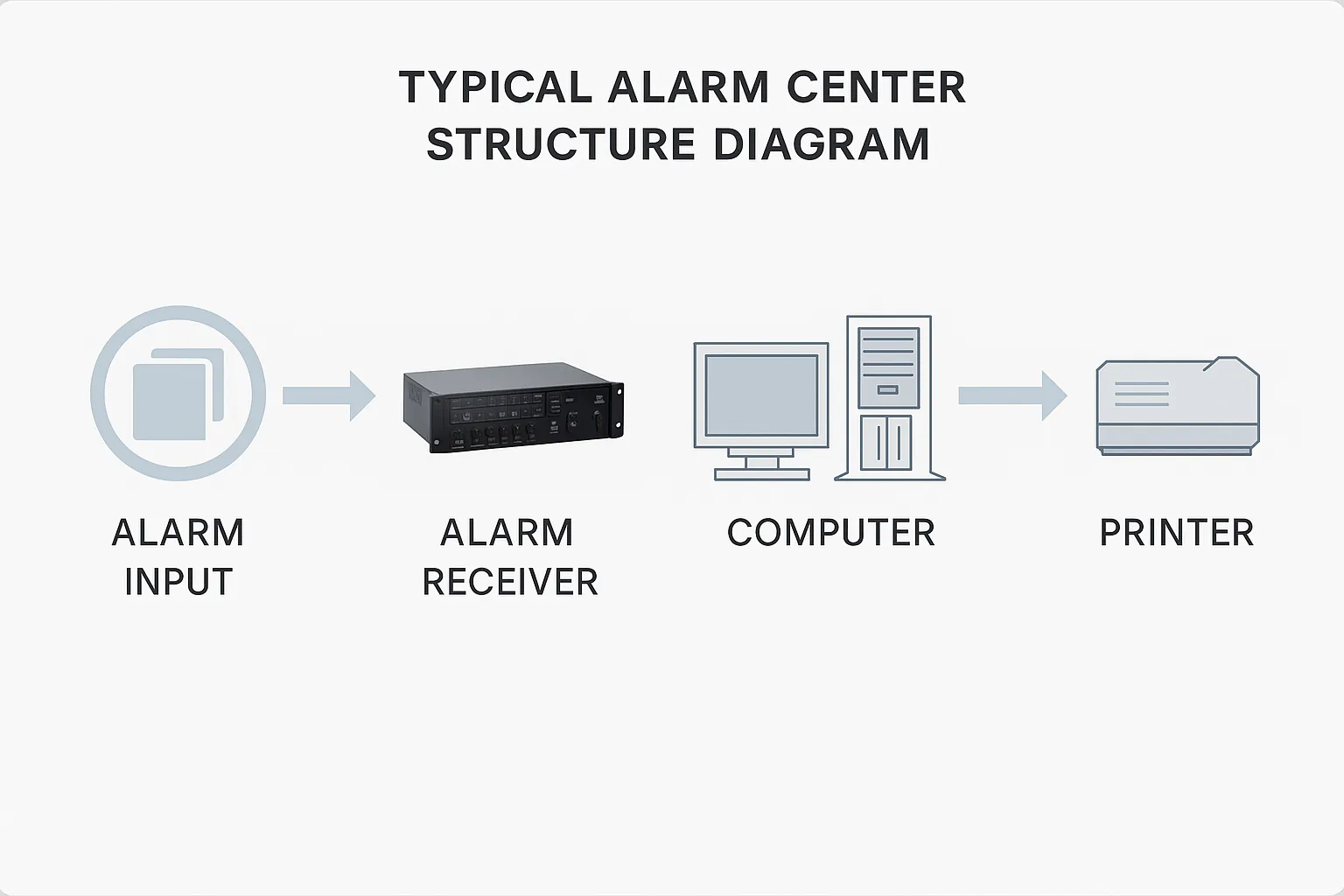
Figure1: Typical alarm center structure diagram
When a front-end detector triggers, the integrated management platform, according to video verification settings, will automatically display the related video. Combining alarm and video systems allows operators to quickly verify whether an alarm is genuine and respond immediately, reducing dispatch resource usage and providing reliable video evidence. When no alarm linkage is active, the center can proactively preview or playback site images.
1.3 System Functions
1) Alarm device access management: The system supports mainstream alarm control panels and allows configuration of alarm hardware and zones. It automatically receives and notifies alarm events.
2) Video verification: When an alarm is reported to the platform, the system immediately displays the alarm and automatically pops up live video for the defined linked area, including configurable pre-alarm seconds for playback, and records in real time.
3) Alarm-linked wall display: Via configuration, alarm images can be sent to video walls. Configure which channels appear, wall resolution, and screen position. When an alarm occurs, associated images display in real time on the specified video wall location for operator awareness.
4) Alarm-linked intercom: Configure alarm points to link to nearby intercom-capable cameras for audio/video interaction between the monitoring center and the front end.
5) Alarm-linked audio: The system supports local voice output to trigger various alarm tones or sirens at the monitoring center. Audio files can be set or recorded for use as audible alerts.
6) Alarm-linked electronic maps: The platform supports Amap (Gaode) and Google Maps. Add user points, surveillance points, and zone points. On alarm receipt, the platform automatically pops up the alarm location and highlights it with an animation.
7) Event query: Query alarm events by type, source, and time range. Results include precise event timing and detailed descriptions.
1.4 System Advantages
1) Supports multiple communication methods: Communication is critical for networked alarm systems. The alarm subsystem supports PSTN, Internet, GPRS, 3G, VPN, and LAN to provide flexible deployment options.
2) Strong compatibility: Compatible with a variety of mainstream alarm control panels and supports integration with IPC, DVR, and NVR video surveillance devices for alarm-video linkage.
3) Easy integration: The system provides an open TCP/IP data interface protocol and supports server or client modes. Alarm information can be forwarded to third-party platforms such as video, fire systems, and emergency-response systems for integrated linkage.
4) High scalability: The system uses a plug-in design that facilitates online upgrades, expansion, and secondary development.