Introduction
Component rework and repair remain essential in prototype validation, high-value product recovery, and field returns. BGA, QFN, LGA, and large-pitch connectors often require complete removal and replacement when X-ray reveals voids, non-wetting, or head-in-pillow defects. Successful rework depends heavily on precise, repeatable solder paste application at the individual component site. Dedicated rework stencils (also called mini-stencils, site-specific stencils, or localized stencils) enable engineers to deposit the exact volume of solder paste only where needed without contaminating adjacent components. This article covers practical techniques, stencil design rules, material choices, positioning methods, and common pitfalls observed during BGA rework and QFN rework.
Why Standard Full-Panel Stencils Are Not Suitable for Rework
Full-panel SMT stencils are optimized for new-board production with uniform 100–150 µm thickness and laser-cut apertures matched to the entire footprint population. During rework, adjacent components are already soldered and cannot tolerate additional paste or flux. A full-panel stencil would bridge over existing parts and create massive solder shorts. Rework stencils solve this by containing apertures for only one component footprint while the rest of the stencil area is solid foil.
Types of Rework Stencils
Understanding the trade-offs between framed vs. frameless stencils is essential for optimizing SMT assembly quality. The specific types available for rework include:
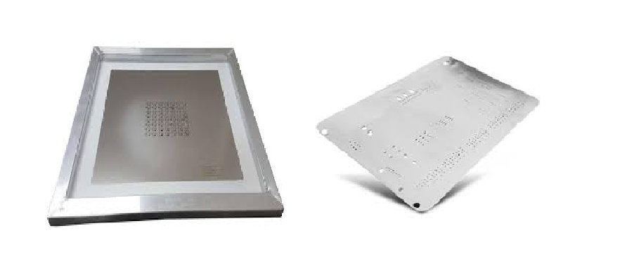
Framed Mini-Stencils
- 150 × 150 mm or 200 × 200 mm aluminum frames
- Stainless steel foil 100–150 µm thick, laser-cut and electro-polished
- Most accurate and repeatable option
- Ideal for high-volume repair or prototype builds with multiple identical boards
Frameless Mini-Stencils (Peel-and-Stick)
- Foil only, with adhesive backing
- Quick to fabricate, lower cost
- Suitable for low-volume or one-off repairs
- Require careful alignment and even pressure
Universal Grid Stencils
- Contain every common BGA pitch (1.27, 1.0, 0.8, 0.5, 0.4 mm) in zones
- Used when exact footprint is unknown or for rapid prototyping
- Higher risk of over-printing on non-target pads
Key Design Rules for Rework Stencils
- Aperture size: Typically 1:1 with pad size for BGA and QFN rework. Some engineers prefer 5–10% reduction to compensate for paste slumping on previously reflowed boards.
- Foil thickness:
- 0.4–0.5 mm pitch BGA → 100–120 µm
- 0.8–1.0 mm pitch BGA → 125–150 µm
- QFN and large thermal pads → 150–200 µm to supply sufficient volume
- Aperture shape for thermal pads: Use segmented or window-pane apertures instead of one large opening to prevent voiding.
- Include at least 5–8 mm of clear foil around the footprint to ensure proper gasket seal.
- Add fiducial marks on the foil that align with board fiducials or adjacent component corners.
- Corner relief cuts or mouse holes for QFN thermal pads improve paste release on thick stencils.
View more about design rules for rework stencils on: The Comprehensive Guide to SMT Stencil Engineering: From Design Optimization to Process Control
Stencil Positioning and Alignment Techniques
Manual Alignment with Magnification
- Use stereo microscope (10–40×) and etched fiducials
- Most common in low-volume repair
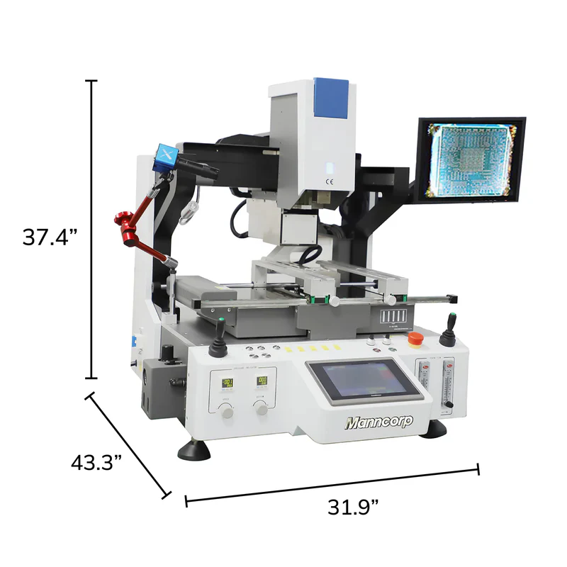
Vacuum Fixture with Vision Overlay
- Custom or universal vacuum plate holds board flat
- Split-vision camera system overlays stencil and PCB fiducials
- Accuracy better than ±25 µm
Mechanical Pin Alignment
- Add tooling holes to framed stencil and matching pins on rework fixture
- Fast and repeatable for production repair
Kapton Tape Edge Guides
- Apply high-temperature tape strips to create a pocket for frameless stencils
- Low-cost method widely used on prototypes
Step-by-Step Localized Solder Paste Application Process
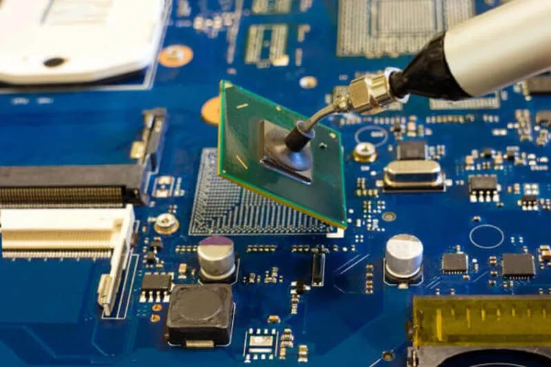
- Remove defective component using hot-air or IR system with proper profile.
- Clean site thoroughly with no-clean flux and wick or vacuum desoldering tool.
- Level and secure PCB in rework fixture.
- Align and secure rework stencil.
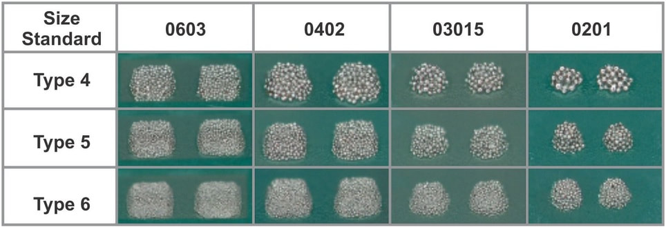
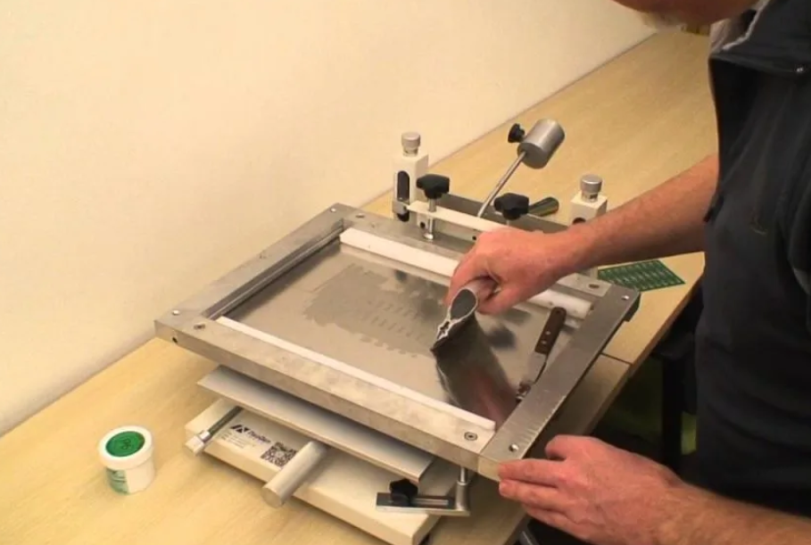
- Apply Type 4 or Type 5 solder paste using a small metal squeegee at 60° angle and minimal pressure.
- Lift stencil straight upward to avoid smearing.
- Inspect paste deposit under microscope for bridging or insufficient volume.
- Place new component using vacuum nozzle with split-vision placement.
- Reflow using component-specific profile (usually lower peak than original assembly).
Special Considerations for QFN Rework
- QFN thermal pads require significantly more paste volume than peripheral pads.
- Use 150–200 µm rework stencils with window-pane aperture design.
- Over-print peripheral pads slightly (110% volume) to ensure fillet formation after center pad reflow.
- Apply tacky flux to center pad before component placement if stencil thickness alone cannot supply enough solder.
Common Failures and Troubleshooting
| Symptom | Likely Cause | Corrective Action |
|---|---|---|
| Paste smears on adjacent pads | Poor gasket seal, warped board | Use vacuum fixture, thicker foil |
| Insufficient volume on BGA | Stencil too thin or apertures reduced too much | Increase thickness or return to 1:1 apertures |
| Bridging on 0.4 mm BGA | Excessive pressure or dull squeegee | Use sharp polyurethane squeegee, light pressure |
| Voiding on QFN center pad | Single large aperture | Switch to window-pane design |
Conclusion
Rework stencils are indispensable tools for reliable BGA rework, QFN rework, and any localized solder paste application. Success depends on correct stencil type selection, precise aperture design, accurate alignment, and controlled printing technique. Framed mini-stencils with fiducials and vacuum fixtures deliver the highest repeatability in production repair environments, while frameless stencils remain valuable for prototypes and field service. Following the practical guidelines above significantly reduces rework defects and improves first-pass yield during component replacement.
FAQs
Q1: Can I use the original production stencil for BGA rework?
A1: No. The original stencil contains apertures for the entire board and will deposit paste on already-populated components, causing massive shorts. A dedicated rework stencil with only the target footprint is required.
Q2: What foil thickness should I choose for 0.5 mm pitch BGA rework?
A2: Most engineers use 100–120 µm stainless steel foil. This provides sufficient volume while maintaining good paste release on fine-pitch apertures.
Q3: Is a framed rework stencil always better than a frameless one?
A3: Framed stencils offer superior planarity, repeatability, and ease of alignment. Frameless stencils are acceptable for occasional prototype repair but lack tension and are more operator-dependent.
Q4: How do I prevent solder paste from sticking to the rework stencil?
A4: Specify electro-polished foil and use a sharp metal or polyurethane squeegee. Apply paste only to the aperture area and wipe the stencil bottom after each print.
References
IPC-7095D — Design and Assembly Process Implementation for BGAs. IPC, 2018.
IPC-7711/7721C — Rework, Modification and Repair of Electronic Assemblies. IPC, 2017.
IPC-J-STD-075 — Classification of Non-IC Electronic Components for Assembly Processes. IPC, 2020.
IPC-TM-650 2.4.28 — Solder Paste Viscosity Measurement. IPC, 2018.