Communication Interfaces — Background
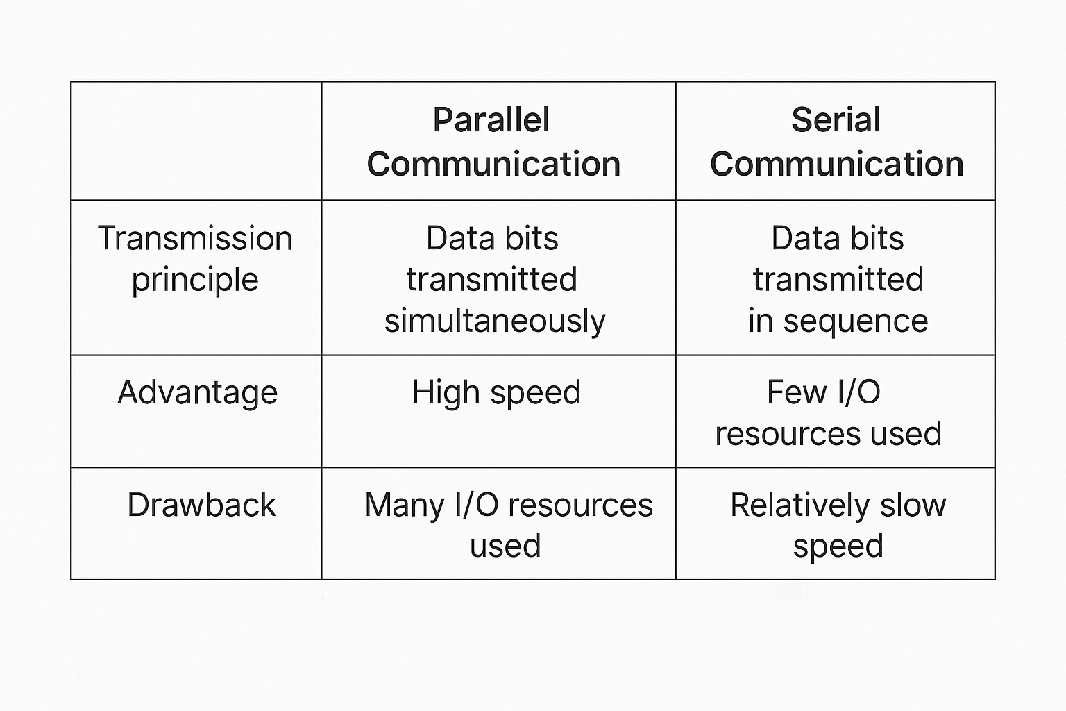
Communication between devices can be classified as parallel or serial. The key differences between parallel and serial communication include wiring, speed, and typical applications.
Types of Serial Communication
1. By data direction:
Simplex: Data flows in only one direction.
Half-duplex: Data can flow in both directions but only one direction at a time. It effectively switches the direction of a simplex link and may use the same port for transmit and receive.
Full-duplex: Data can flow simultaneously in both directions. Full-duplex is equivalent to two simplex links and requires separate transmit and receive paths.
2. By synchronization method:
Synchronous communication: Uses a clock signal to synchronize transfer, e.g. SPI and I2C.
Asynchronous communication: Does not use a clock line. Examples include UART (universal asynchronous transceiver) and single-wire protocols.
In synchronous links, a shared clock line coordinates when data lines are sampled, commonly at a clock rising or falling edge. In asynchronous links, timing is embedded in the data stream using framing bits, and both ends must agree on the transmission rate (baud rate). Typical baud rates include 4800, 9600, and 115200 bps.
Synchronous communication generally has higher efficiency because most transmitted bits are payload. Asynchronous communication includes framing and synchronization bits, which reduces payload efficiency but tolerates larger clock deviations between sender and receiver.
STM32 Serial Interface Basics
STM32 devices provide UART (universal asynchronous receiver/transmitter) and USART (universal synchronous/asynchronous receiver/transmitter) interfaces. For larger devices such as the STM32F10x series, the family typically includes 3 USARTs and 2 UARTs.
UART Pin Connections
RXD: Data input pin, used for receiving data.
TXD: Data output pin, used for transmitting data.
When connecting two microcontrollers, tie grounds together and cross TXD and RXD: microcontroller 1 RXD connects to microcontroller 2 TXD, and microcontroller 1 TXD connects to microcontroller 2 RXD. This enables TTL-level communication. For an example of STM32 communicating with an 8051 microcontroller, see relevant application notes.
When connecting a microcontroller to a PC (host), you cannot directly cross TXD/RXD if the PC uses an RS-232 interface. Although both sides have TXD and RXD signals, the voltage standards differ. PC serial ports typically use RS-232 levels (often DB9), so you need a level translator between the microcontroller TTL signals and the RS-232 signals before crossing TX/RX.
Typical voltage levels:
Microcontroller TTL levels: +5 V represents logic 1, 0 V represents logic 0.
RS-232 levels: +13 to +15 V represent logic 0, -13 to -15 V represent logic 1.
The RS-232 serial connection architecture is typically implemented by a level translator IC such as MAX232 to convert between TTL and RS-232 voltages.
Use a level converter like the MAX232 between the microcontroller UART pins and the PC RS-232 connector to achieve proper voltage translation.
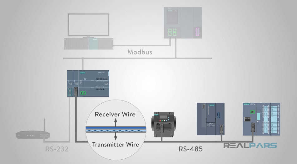
RS-232 Overview
The 9-pin connector on many desktop PCs is a COM port (serial port). In industrial control and data acquisition, RS-232 with DB9 packaging is common. Only a few pins are used for basic communications:
Pin 2: PC RXD (input)
Pin 3: PC TXD (output)
Pin 5: Ground
Using pins 2 and 3 enables full-duplex asynchronous serial communication.
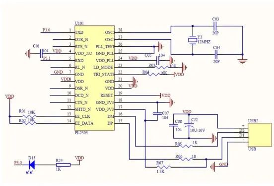
Microcontroller UART pins must be connected in a crossed manner to the PC RS-232 port via a level translator. If a PC lacks an RS-232 port and only has USB, a USB-to-serial adapter can be used; the adapter requires a driver that typically interfaces with a chip such as PL2303 to convert between RS-232 and USB signaling.
STM32 UART Characteristics
Full-duplex asynchronous communication.
Fractional baud-rate generator for accurate baud rates. Sender and receiver share a programmable baud-rate, supporting up to 4.5 Mbits/s.
Programmable data length (8 or 9 bits).
Configurable stop bits (1 or 2 bits supported).
Support for DMA multi-buffer communication.
Separate enable bits for transmitter and receiver.
Status flags include: receive buffer not empty, transmit buffer empty, and transmission complete.
Multiple interrupt sources with flags for triggering.
Additional features: parity control and four error-detection flags.
UART Parameters in STM32
Asynchronous UART data framing requires agreement on start bits, data bits (8 or 9), parity bit (optional, often the 9th bit), stop bits (1, 1.5, or 2), and baud rate. The data packet format must match between sender and receiver for reliable transfer.
Typical UART frame: 1 start bit + 8 data bits + optional parity bit + 1 stop bit.
Parity can be odd or even. Odd parity means the total number of 1 bits in the data bits plus the parity bit is odd. Even parity means the total number of 1 bits is even. Other parity modes include forced 0 (space), forced 1 (mark), or no parity. In mark or space parity modes, the parity bit is always 1 or always 0 respectively, regardless of the data content.
UART (USART) Block Diagram
The block diagram divides into top, middle, and bottom sections. Data entering RX goes into the receive shift register, then the receive data register, where it can be read by the CPU or DMA. Data from the CPU or DMA goes into the transmit data register, then the transmit shift register, and out via TX.
Both transmit and receive operations are timed by clocks derived from a shared baud-rate generator. Even though asynchronous links do not use an external clock line, the UART provides internal transmitter and receiver clocks. These clocks are driven by a common control unit and the baud-rate divider calculation. The receiver clock and transmitter clock share the baud-rate generator, which determines the timing used by the shift registers.