Why Are PCB Fuses Essential for Overcurrent Protection?
In the rapidly evolving landscape of electronics, safeguarding printed circuit boards (PCBs) from damaging overcurrent events is paramount for ensuring device longevity and user safety. PCB fuses serve as a primary defense mechanism, protecting sensitive electronic components from potential harm caused by short circuits, excessive loads, or unexpected voltage spikes. The judicious selection of the appropriate fuse for a PCB design can be the deciding factor between a resilient, long-lasting product and frequent, costly failures. This guide delves into the fundamental aspects of PCB fuses, exploring their various types, crucial selection criteria, and recommended practices to assist engineers in making well-informed decisions.
Regardless of whether you are developing consumer gadgets, automotive systems, or heavy industrial machinery, a deep understanding of fuse selection is indispensable for optimizing both performance and safety. Let’s explore the nuances of overcurrent protection and how to identify the ideal PCB fuse for your specific application.
The Role of a PCB Fuse
A PCB fuse is a compact, intentionally designed sacrificial component directly integrated onto a circuit board to shield circuits from excessive electrical current. When the current flowing through the circuit surpasses the fuse's specified rating, its internal element—typically a thin metal wire or strip—rapidly melts. This action effectively breaks the circuit, thereby preventing damage to subsequent components. This swift interruption of current flow minimizes risks such as overheating, permanent component failure, or even potential fire hazards. For instance, within a smartphone's PCB, a fuse can protect delicate integrated circuits (ICs) from a short circuit originating from a faulty battery, preserving the device's operational integrity.
Without adequate overcurrent protection, an uncontrolled surge of current can cause severe damage, including melting solder joints, burning PCB traces, or irrevocably harming integrated circuits. Industry analyses suggest that overcurrent incidents contribute to approximately 30% of electronic device failures, underscoring the vital role fuses play in PCB design. By acting as a controlled weak link, fuses ensure that electrical faults are contained and isolated before they can propagate and cause widespread system damage.
Exploring the Different Types of PCB Fuses
PCB fuses are manufactured in various forms, each tailored to specific applications and performance needs. A thorough understanding of these options is crucial for making an informed selection for your design. Here are the most prevalent types of PCB fuses:
Surface-Mount Device (SMD) Fuses
Surface-mount fuses are compact components designed to be soldered directly onto the PCB's surface. Their small size makes them exceptionally well-suited for high-density, modern electronic devices such as smartphones and laptop computers. Available in standard package dimensions (e.g., 1206, 0805), SMD fuses typically offer current ratings from 0.5A up to 10A and voltage ratings reaching 250V. Their minimal footprint and compatibility with automated assembly processes render them a highly popular choice for designs where space is a critical constraint.
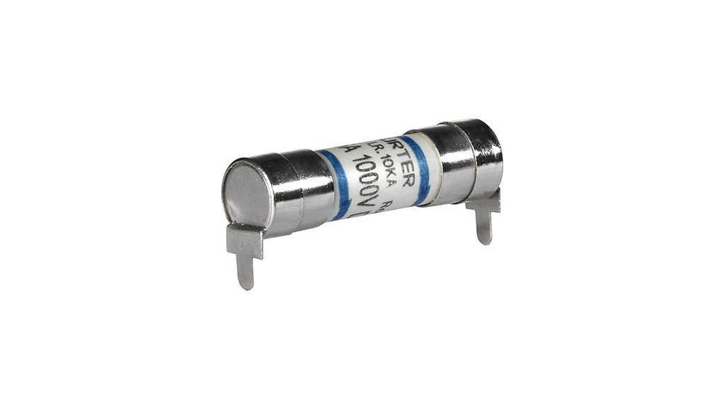
Through-Hole Fuses
Through-hole fuses feature wire leads that are inserted into drilled holes on the PCB and then soldered. These fuses are commonly employed in applications demanding greater mechanical robustness, such as industrial control systems. Through-hole fuses are generally easier to replace manually and can accommodate higher current ratings, frequently up to 20A. However, their larger physical size makes them less suitable for compact electronic designs.
Resettable (PTC) Fuses
Polymeric Positive Temperature Coefficient (PPTC) fuses, often referred to as resettable fuses, possess a distinctive characteristic: they do not require replacement after an overcurrent event. When an excessive current flows, the polymer material within the fuse heats up, leading to a significant increase in its electrical resistance, which effectively limits the current flow. Once the fault condition is resolved and the fuse cools down, it automatically resets to its low-resistance state. These fuses are particularly well-suited for applications prone to frequent, brief current surges, such as USB ports or telecommunications equipment, with typical trip currents ranging from 0.1A to 5A.
Fast-Blow vs. Slow-Blow Fuses
Fuses are also categorized based on their response time to overcurrent conditions. Fast-blow fuses react almost instantaneously when an overcurrent is detected. This rapid response makes them ideal for safeguarding extremely sensitive components like microcontrollers, where even a momentary surge could cause irreparable damage. Conversely, slow-blow fuses are engineered to tolerate temporary current surges—such as the inrush currents that occur when charging capacitors or starting motors—without tripping. They are typically found in power supplies or motor drive circuits. For example, a 2A slow-blow fuse might safely withstand a 4A surge for 100 milliseconds before blowing.
Essential Criteria for Selecting a PCB Fuse
Choosing the correct PCB fuse necessitates a meticulous evaluation of various electrical and environmental factors. Here is a detailed breakdown of the critical parameters to consider during the selection process:
Current Rating
The current rating specifies the maximum continuous current that a fuse can safely carry without interrupting the circuit. To select an appropriate rating, first determine the circuit's normal operating current. Then, add a safety margin, typically 20-25%, to this value. For instance, if a circuit normally draws 1.6A, a 2A fuse would offer adequate protection while preventing unwanted "nuisance" tripping. Selecting a fuse with too low a rating can lead to frequent blowouts, whereas an oversized fuse may provide insufficient protection in a fault condition.
Voltage Rating
The voltage rating indicates the maximum voltage at which the fuse can safely and effectively interrupt a current. This rating must be equal to or greater than the circuit's maximum operating voltage. For example, a 12V automotive PCB should utilize a fuse with a rating of at least 12V, though higher ratings like 32V or 125V are often used for an added layer of safety. Using a fuse with an insufficient voltage rating risks arcing across the fuse element or a complete failure to break the circuit during an overcurrent event.
Breaking Capacity (Interrupting Rating)
Breaking capacity, also known as interrupting rating, refers to the maximum fault current that a fuse can safely interrupt without experiencing catastrophic failure itself. In high-power electrical systems, short-circuit currents can escalate to thousands of amperes. A typical SMD fuse might have a breaking capacity of 50A at 32V, while industrial-grade fuses can be designed to handle fault currents up to 10,000A. It is imperative to always ensure that the fuse's breaking capacity exceeds the absolute worst-case fault current anticipated in your circuit.
Response Time (Time-Current Curve)
The fuse's time-current curve illustrates its characteristic response time to varying levels of overcurrent. Fast-blow fuses are ideal for highly sensitive electronic circuits, reacting within milliseconds to protect delicate components. In contrast, slow-blow fuses are engineered to tolerate transient surges, making them suitable for circuits that exhibit high inrush currents, such as those with motors or large capacitive loads. Carefully review the circuit's operational requirements and the tolerance levels of its components to select the most appropriate response time.
Environmental Considerations
The operating environment, including factors like temperature, humidity, and mechanical vibration, can significantly impact a fuse's performance and longevity. For instance, fuses used in harsh automotive or marine applications may need to be rated for extreme temperature ranges (e.g., -40°C to 125°C) or be resistant to moisture. Specialized sealed fuses or those constructed with low-inductance materials are designed to perform reliably in such challenging conditions. Always consult the fuse's datasheet for its specific environmental ratings.
Suggested Reading: Choosing the Right PCB Fuse for Overcurrent Protection
Best Practices for Integrating Fuses into PCB Designs
Properly integrating fuses into a PCB design is crucial for enhancing circuit reliability and simplifying future maintenance. Adhering to these best practices will help optimize your design:
● Proximity to Power Source: Position the fuse as close as practically possible to the circuit's power input (e.g., battery connector or power supply input). This strategic placement ensures that the entire downstream circuit is protected from an overcurrent event, minimizing the risk of widespread damage.
● Accessibility for Maintenance: For through-hole or user-replaceable fuses, ensure they are easily accessible for inspection, testing, and replacement. In compact designs, SMD fuses are typically installed during automated assembly processes.
● Thorough Testing: Conduct continuity and electrical functionality tests during the PCB assembly phase to confirm that the fuse operates within its specified parameters before the device is deployed.
● Expert Consultation: For complex or mission-critical applications, collaborate with experienced engineers or manufacturing specialists to validate your fuse selection. Their insights can help prevent costly design oversights.
● Adherence to Standards: Ensure that all selected fuses comply with relevant industry safety and reliability standards, such as those set by UL (Underwriters Laboratories) or IEC (International Electrotechnical Commission).
Common Errors to Avoid in Fuse Selection and Integration
Even seasoned engineers can make mistakes when choosing or integrating PCB fuses. Being aware of these common pitfalls can help prevent issues:
● Underestimating Inrush Currents: Failing to account for temporary inrush currents can lead to annoying "nuisance" tripping of the fuse. It's advisable to use slow-blow fuses in circuits with known inrush characteristics or to carefully consult component datasheets to estimate peak current demands.
● Disregarding Breaking Capacity: Selecting a fuse with an insufficient breaking capacity can have severe consequences. If the fuse cannot safely interrupt a high fault current, it may fail catastrophically, leading to further damage or posing significant safety hazards.
● Neglecting Derating Factors: High ambient operating temperatures reduce a fuse's effective current-carrying capacity. Always apply appropriate derating factors (e.g., a 0.8x derating for environments operating at 85°C) to ensure reliable long-term operation.
● Using Non-Certified Fuses: Opting for uncertified or low-quality fuses can result in inconsistent performance, thereby compromising overall circuit safety and reliability. Always source fuses from reputable, established manufacturers.
AIVON's Support for Your PCB Fuse Integration Needs
At AIVON, one of the largest online PCB manufacturer, we fully recognize the critical importance of robust overcurrent protection in PCB design. Our state-of-the-art manufacturing capabilities and rapid prototyping services are designed to empower engineers to meticulously test and refine fuse integration with utmost precision. Through our global logistics network and unwavering commitment to high-quality standards, we deliver PCBs that precisely match your specifications, whether your design is for sophisticated consumer electronics or demanding industrial applications. Our team of experts is also readily available to offer guidance on component selection, ensuring that your chosen fuses align perfectly with your circuit's specific requirements.
Conclusion: Ensuring Reliability with Optimal PCB Fuse Selection
The selection of the correct PCB fuse is a crucial step in designing reliable and safe electronic systems. By understanding the different fuse types, current and voltage ratings, and response characteristics, engineers can effectively protect circuits from overcurrent and potential failures. Beyond selecting the right specifications, attention should also be given to fuse placement, operating environment, and quality standards to ensure consistent performance. A well-chosen fuse not only prevents damage and extends product lifespan but also enhances overall system reliability and compliance with safety regulations—making it an essential component in achieving durable and efficient PCB designs.