Overview
When purchasing an LED display, unfamiliar technical terms can cause confusion. The following is a concise list of 55 common LED display terms and their definitions.
Terms and Definitions
1. What is LED? LED stands for light emitting diode, a diode that emits visible light.
2. Pixel A pixel is the smallest luminous unit of an LED display, equivalent to the pixel concept used in regular computer monitors.
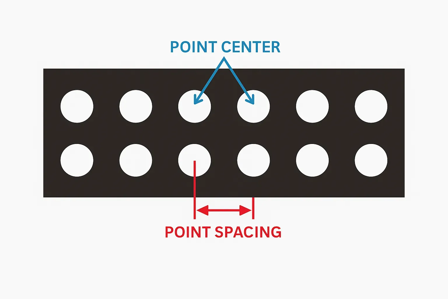
3. Pixel pitch The center-to-center distance between two adjacent pixels. Smaller pitch corresponds to a shorter recommended viewing distance. Industry shorthand is "P".
4. Pixel density Also called dot density; usually expressed as the number of pixels per square meter.
5. LED module (unit board) The smallest structural unit of an LED display that contains several display pixels and can be assembled into a larger screen. Typical modules are 8×8, 8×7, etc., with defined circuitry and mounting structure.
6. DIP DIP is the abbreviation of double in-line package, a dual-row through-hole mounting style.
7. SMD/SMT SMT stands for surface mount technology; SMD refers to surface mounted devices. SMT is the most common electronic assembly technology for LED packages mounted on the PCB surface.
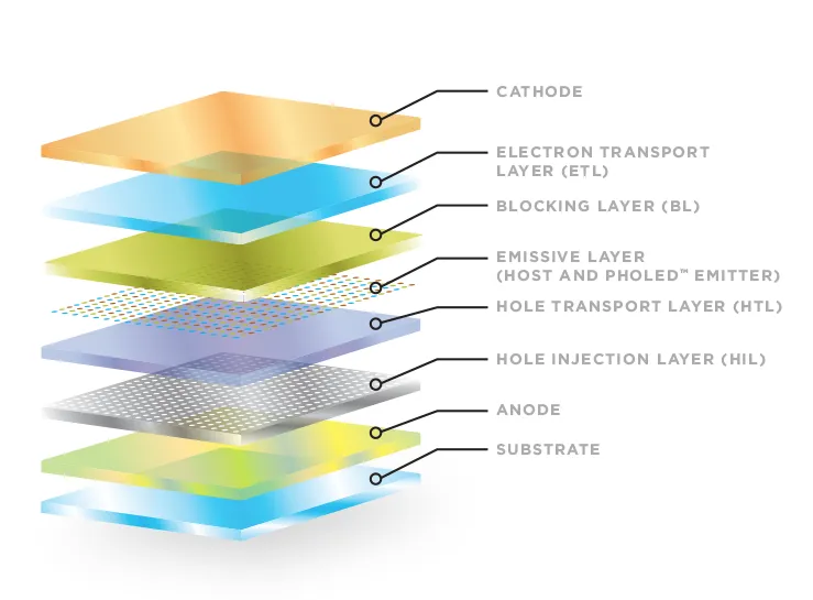
8. LED display A screen composed of an array of LED devices driven by control electronics to present images or text.
9. Through-hole (plug-in) A through-hole process where DIP-packaged LEDs have leads inserted through the PCB and soldered. Advantages: high brightness and good heat dissipation. Disadvantage: lower pixel density.
10. Surface-mount module Advantages and disadvantages Surface-mount modules use SMT LEDs soldered to the PCB surface without leads passing through. Advantages: better display quality and higher pixel density, suitable for indoor viewing. Disadvantages: lower peak brightness and less LED self-dissipation.
11. 3-in-1 package Refers to an SMT package that vertically combines RGB chips in one package. It integrates advantages of combined packages but can complicate the manufacturing and maintenance process.
12. 3-by-1 (three separate packages) Refers to three independent SMT LED packages for R, G, B arranged with a defined spacing to achieve color mixing while alleviating some drawbacks of 3-in-1 packaging.
13. Bicolor, pseudo-color, full-color Displays can be built with LEDs of different colors. Bicolor uses two colors (for example red and green or red and yellow-green). Pseudo-color uses three colors such as red, yellow-green, and blue. Full-color uses red, pure green, and pure blue.
14. Luminance The luminous intensity emitted per unit area of an LED display, typically expressed in cd/m2 (candela per square meter).
15. Brightness levels The number of manual or automatic steps available to adjust the screen brightness from minimum to maximum.
16. Gray levels Within a given brightness level, the number of discrete steps between the darkest and brightest outputs, often described in various ways.
17. Maximum brightness The maximum brightness of each primary color at maximum drive and highest gray level under a specific ambient illuminance.
18. Moiré pattern Moiré refers to irregular ripple-like artifacts that can appear when video is filmed or sampled from a full-color LED display.
19. PCB PCB stands for printed circuit board, the board on which electronic components are mounted.
20. Module dimensions The physical size of a module, usually expressed as length × width in millimeters (for example: 48 × 244).
21. Module resolution The number of pixels in a module, typically expressed as rows × columns (for example: 64 × 32).
22. BOM BOM is the abbreviation of bill of material, the parts list for a product.
23. White balance White balance refers to the relative brightness ratio of RGB colors. Adjusting the RGB brightness ratios and white coordinate is called white balance adjustment.
24. Contrast ratio The ratio between the display's maximum brightness and the background brightness under a given ambient illuminance.
25. Color temperature The temperature of a black body whose emitted color matches that of the light source; commonly used to describe the perceived "warmth" or "coolness" of light.
26. Color deviation Color differences arise because R, G, B emitters use different materials and have varying viewing angle spectral distributions; observable differences are called color deviation. Color can change when viewed from different angles.
27. Frame rate The number of times per second that the display image content is updated. Typical frame rate is around 60 frames per second, which is imperceptible to the human eye.
28. Refresh rate The number of times per second the displayed image is refreshed. Higher refresh rates produce smoother images.
29. Viewing angle, visible angle, optimal viewing angle Viewing angle is the angle between a viewing direction and the display normal when brightness drops to half that of the normal direction; usually specified separately for horizontal and vertical. Visible angle describes the directions from which the image can still be seen. Optimal viewing angle is the direction where the image appears clearest and without color shift.
30. Optimal viewing distance The vertical distance from the viewer to the screen at which the image is fully visible, with minimal color shift and maximum clarity.
31. Faulty pixels A pixel whose luminous state does not match control requirements. Fault types include dead pixels (no light), always-on pixels (stuck bright or dim), and flickering pixels.
32. Static drive vs. scanning drive Static drive means each pixel is driven "point-to-point" from the driver IC outputs, requiring no row scan circuitry. Scanning drive controls pixels by rows or columns and requires row control circuitry. Static drive typically offers better display quality, stability, and less brightness loss but higher cost; scanning drive reduces cost but may degrade display quality and brightness.
33. Constant-current drive vs. constant-voltage drive Constant-current drive maintains a fixed current within the driver IC's operating range. Constant-voltage drive maintains a fixed voltage within the driver IC's operating range.
34. Typical aspect ratios For text-and-graphic displays, the ratio depends on content. For video displays, common ratios are 4:3 or close to 4:3; an ideal ratio for widescreen content is 16:9.
35. Control system pixel capacity Examples: Communication card A: single-color or dual-color 1024 × 64; card B: single-color 896 × 512, dual-color 896 × 256; DVI dual-color: 1280 × 768; DVI full-color: 1024 × 512.
36. Nonlinear correction If a computer's digital output is displayed directly on an LED display without correction, color distortion can occur. Nonlinear correction applies a nonlinear function to the computer output within the control electronics to generate the correct display signals.
37. Rated operating voltage, operating voltage, supply voltage Rated operating voltage is the voltage at which a device is intended to operate normally. Operating voltage is the voltage value during normal operation within the rated range. Supply voltages may be AC or DC. Mains AC is typically AC 220V–240V; common DC supplies include 5 V DC and 12 V DC; solar supplies are often 12 V.
38. Color distortion The perceptual difference between the real object's appearance and its reproduction on the display.
39. Synchronous vs. asynchronous systems Synchronous systems display content in real time, synchronized with a computer monitor. Asynchronous systems store preedited display data in the screen controller so the display can operate without a connected computer.
40. Dead-pixel detection technology Software and hardware that detect open or shorted LEDs on the screen and generate reports for screen administrators is called dead-pixel detection technology.
41. Power-supply monitoring Technology that monitors the status of the display's power supplies and reports their operating conditions to administrators.
42. Ambient light detection and brightness adjustment Ambient light detection measures the environment brightness around the display using a light sensor. Brightness adjustment uses the measured data to adjust the display's emitted brightness via the control system or control computer.
43. Real pixel vs. virtual pixel Real pixels: one-to-one correspondence between physical pixels and displayed pixels. Virtual pixels: the physical-to-displayed pixel ratio is 1:N (N=2 or 4), allowing the displayed image to appear as 2× or 4× the physical pixel count. Virtualization can be implemented in software or hardware, and examples include 1R1G1B virtual and 2R1G1B virtual configurations based on module LED arrangements.
44. Remote control "Remote" does not always mean long distance. Remote control can be within the same local area network or between geographically distant endpoints. Use remote control when the control location exceeds direct connection range.
45. Fiber optic transmission vs. Ethernet cable transmission Fiber transmission converts electrical signals to optical signals for transmission over glass fiber. Ethernet cable transmission uses metallic conductors for electrical signal transmission.
46. When to use Ethernet cable or fiber Use Ethernet cable when the wiring distance between the display and control computer is less than 100 meters. Use multimode fiber for distances greater than 100 meters and less than about 500 meters. Use single-mode fiber for distances beyond approximately 500 meters.
47. LAN control vs. Internet control LAN control uses one computer within a local area network to control another computer or external device. Internet control uses the controller's IP address on the Internet to reach and control the target device.
48. DVI vs. VGA DVI stands for Digital Video Interface, a common digital video signal interface. VGA (Video Graphics Array) is an analog display standard introduced by IBM for computer display output.
49. Digital signal and digital circuit A digital signal has discrete amplitude levels, usually represented by 0 and 1. Circuits that process and control such signals are called digital circuits.
50. Analog signal and analog circuit An analog signal has continuous amplitude values over time. Circuits that process such signals are called analog circuits.
51. PCI slot PCI is the peripheral component interconnect bus. The PCI slot on a motherboard is a main expansion slot for adding peripheral cards to provide additional computer functions.
52. AGP slot AGP stands for accelerated graphics port. It is an interface designed to improve the speed and smoothness of 3D graphics on personal computers by providing direct access to main memory for texture mapping, double buffering, and alpha blending.
53. GPRS, GSM, CDMA GPRS (general packet radio service) provides packet-switched data over existing GSM networks and is commonly used for wireless data communication. GSM stands for Global System for Mobile Communications, a digital cellular standard. CDMA (code division multiple access) is a wireless communication technology based on spread-spectrum techniques.
54. Use of GPRS for displays GPRS-enabled modules can transmit small amounts of data over mobile networks, enabling remote point-to-point data transfers for remote control of LED displays.
55. USB interface USB stands for Universal Serial Bus, a serial interface that supports hot-plugging and connects up to 127 peripheral devices. Common standards include USB 1.0 and USB 2.0.