OLED technology demands highly specialized PCBs that integrate precise current-drive circuitry, thermal management, and high-speed signal routing to deliver stable, high-resolution images. Unlike conventional LED backlights, OLED panels emit light directly from organic layers, placing extreme requirements on PCB layout, power integrity, and material selection. Aivon's expertise in multilayer and flexible PCB manufacturing ensures these boards meet the electrical, thermal, and reliability demands of modern OLED applications in consumer electronics, automotive displays, and industrial instrumentation.
OLED Panel Architecture and PCB Backplane Integration
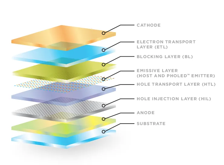
An OLED panel consists of a thin-film transistor (TFT) backplane, organic emissive layers, and a cathode, all typically fabricated on glass or flexible polyimide substrates. The PCB serves as the critical interface between this display stack and the system controller. Designers must route thousands of data and scan lines with controlled impedance to prevent signal degradation at refresh rates above 120 Hz.
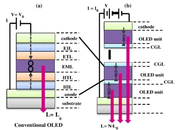
Key stack-up decisions include dedicating inner layers for low-impedance power planes that supply constant current to each sub-pixel. High-Tg FR4 or polyimide-based PCBs with 2–3 oz copper are commonly selected to handle the localized heat generated by active-matrix OLED (AMOLED) drivers while maintaining dimensional stability during lamination and reflow.
Essential Technical Concepts for OLED PCB Design
Engineers working with OLED modules encounter several core parameters that directly influence PCB layout rules:
- Pixel Pitch and Resolution dictate trace density and via placement; finer pitches (under 0.5 mm) require HDI microvias and sequential lamination to maintain signal integrity.
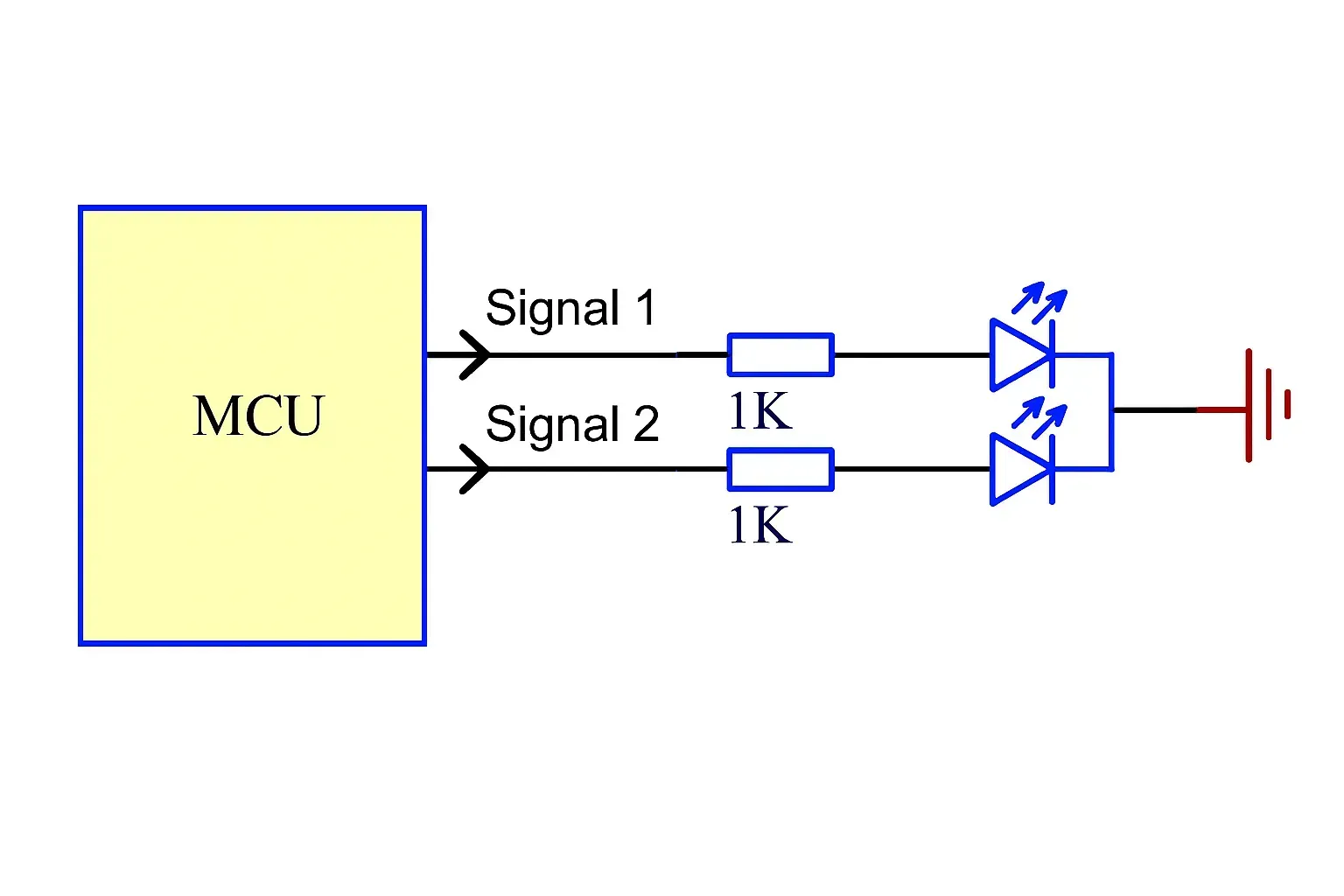
- Current Density and PWM Dimming demand wide, low-resistance copper traces and careful decoupling capacitor placement to minimize voltage droop and electromagnetic interference.
- Lifetime and Burn-In considerations translate into PCB-level thermal vias and heat-spreading planes that keep junction temperatures below critical thresholds where organic materials degrade.
- Color Gamut and Sub-Pixel Rendering rely on precise timing of RGB drive signals, achieved through matched-length differential pairs and proper termination on the control PCB.
These parameters guide every aspect of schematic capture and layout, ensuring the finished board supports both visual performance and long-term reliability.
Achieving High Color Purity: PCB Layout Challenges and Solutions
High color purity in OLEDs depends on stable drive currents and minimal crosstalk between adjacent sub-pixels. On the LED PCB, this requires strict separation of analog current sources from digital control logic, combined with continuous ground planes and via stitching to suppress noise.
Thermal gradients across the panel can shift emission spectra; therefore, PCB designers incorporate copper pours and thermal vias under driver ICs, often using metal-core substrates for high-brightness applications. Electromagnetic compatibility (EMC) techniques such as ferrite beads on supply lines and shielding cans over high-speed serializers further protect color accuracy in environments with strong RF fields.
Manufacturing processes must also address these challenges. Controlled-impedance etching and precise registration during multilayer lamination ensure repeatable performance across production volumes, while advanced surface finishes like ENIG or OSP maintain low contact resistance at the flexible PCB-to-panel connectors.
Reliability, Thermal Management, and Manufacturing Implications
OLEDs are particularly sensitive to heat and moisture. PCB material selection therefore favors high-Tg laminates with low moisture absorption, and designs incorporate redundant power paths and conformal coatings for harsh environments. Via-in-pad technology and laser-drilled microvias enable the dense interconnects required for 4K and 8K OLED modules without compromising mechanical strength.
Cross-industry applications—ranging from automotive instrument clusters to medical imaging monitors—further emphasize the need for automotive-grade PCBs with extended temperature ratings and rigorous reliability testing. By integrating these considerations early in the design phase, engineers can prevent common failure modes such as pixel dropout, color shift, and premature panel degradation.
Conclusion
Through disciplined PCB engineering focused on current-drive precision, thermal dissipation, and signal integrity, OLED display systems achieve superior image quality and extended operational life. Aivon’s manufacturing capabilities in HDI, flexible, and metal-core PCBs provide the foundation for next-generation OLED products that meet both performance and production requirements.