LED lighting systems require carefully engineered PCBs that manage current regulation, thermal dissipation, and precise control signals to ensure reliable performance across indoor, outdoor, and industrial applications. From basic series-parallel arrays to advanced driver ICs and microcontroller-based dimming, every PCB layout decision directly affects efficiency, lifespan, and compliance with safety standards. Aivon’s multilayer and high-voltage PCB manufacturing capabilities deliver the necessary copper thickness, creepage distances, and thermal vias that modern LED circuits demand.
LED Operation Fundamentals and PCB Layout Implications
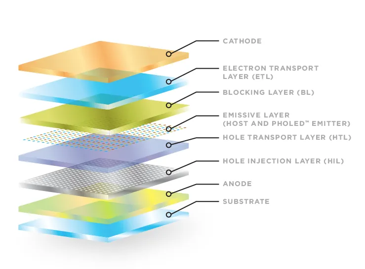
LEDs function as constant-current devices whose forward voltage and luminous output vary with temperature and drive current. On the PCB, designers must implement constant-current paths rather than simple voltage sources. This begins with wide, low-resistance copper traces sized according to expected current density, typically using 2 oz or heavier copper for loads above 500 mA. Thermal reliefs and arrays of thermal vias under LED footprints transfer heat to inner copper planes or external heatsinks, preventing junction-temperature rise that shortens LED life.

Constant-Current Driver ICs on PCB: U6117D Integration
The U6117D family provides integrated constant-current regulation for LED strings up to several hundred milliamps. Successful PCB implementation requires placing the IC close to the LED array to minimize trace inductance and voltage drop. Decoupling capacitors (10 µF ceramic plus 0.1 µF) sit immediately adjacent to the supply pins, while the current-setting resistor connects via the shortest possible path to avoid noise pickup. For dimming applications, PWM signals route on dedicated layers with controlled impedance to preserve edge rates and prevent flicker.
Series and Parallel LED Configurations on High-Voltage PCBs
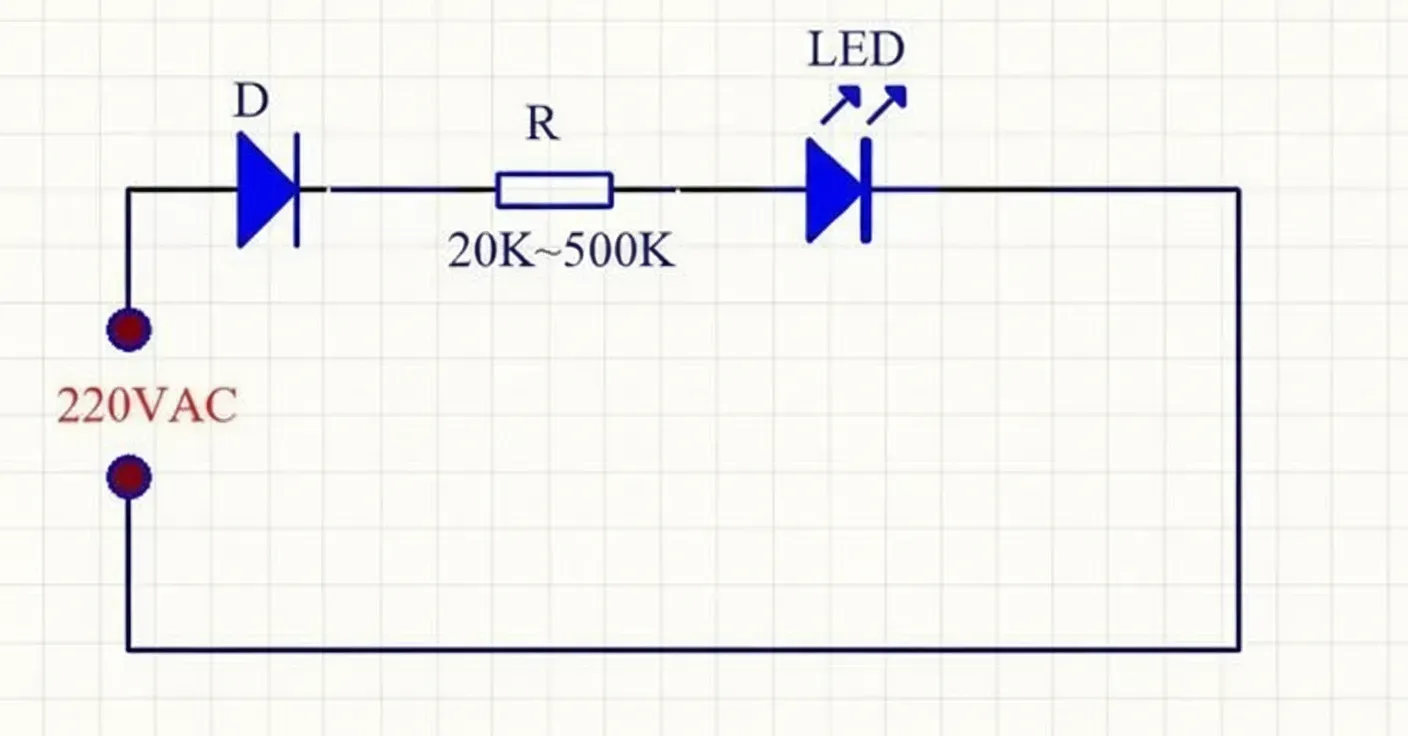
Direct 220 V AC LED circuits combine series strings with parallel branches to match mains voltage while balancing current. PCB design must address high-voltage safety: minimum 6 mm creepage and 3 mm clearance between live traces and ground, plus reinforced insulation where required. Series resistors or capacitive droppers are replaced on the board by constant-current ICs or linear regulators mounted on metal-core substrates for better heat spreading. Parallel branches use matched trace lengths and star-point current distribution to equalize brightness and avoid hot-spotting.
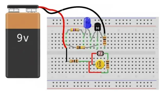
Low-Power LED Night-Light PCB Design
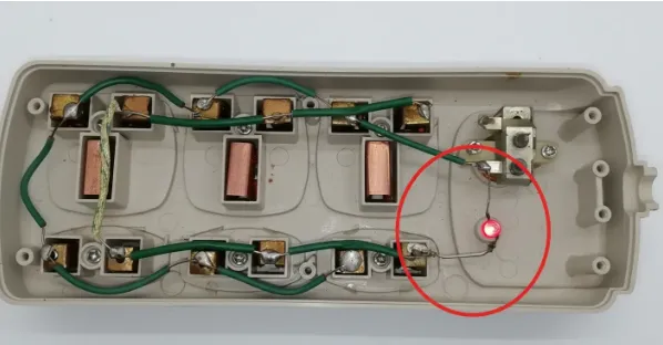
Compact night-light circuits typically operate at 5–12 V with currents below 20 mA. The PCB can be single- or double-sided with standard FR4, yet still benefits from proper grounding and EMI filtering. A simple bridge rectifier, filter capacitor, and linear or switching regulator occupy minimal board area when components are placed to shorten high-current loops. Light-sensor integration (LDR or photodiode) requires analog traces shielded from digital or mains-coupled noise, achieved through ground pours and via stitching.
Microcontroller LED Control: 8051-Based PCB Implementation
The classic 8051 microcontroller drives LEDs through GPIO ports for blinking, chasing, or PWM dimming sequences. LED PCB layout isolates the microcontroller from high-current LED drivers by using separate power domains and a single-point ground connection. Short, wide traces carry the LED current, while crystal and reset lines receive careful routing to maintain signal integrity. For multi-LED arrays, port expansion via shift registers or dedicated LED driver ICs reduces pin count and allows denser layouts using HDI microvias when board size is constrained.
Thermal Management, Reliability, and Manufacturing Considerations
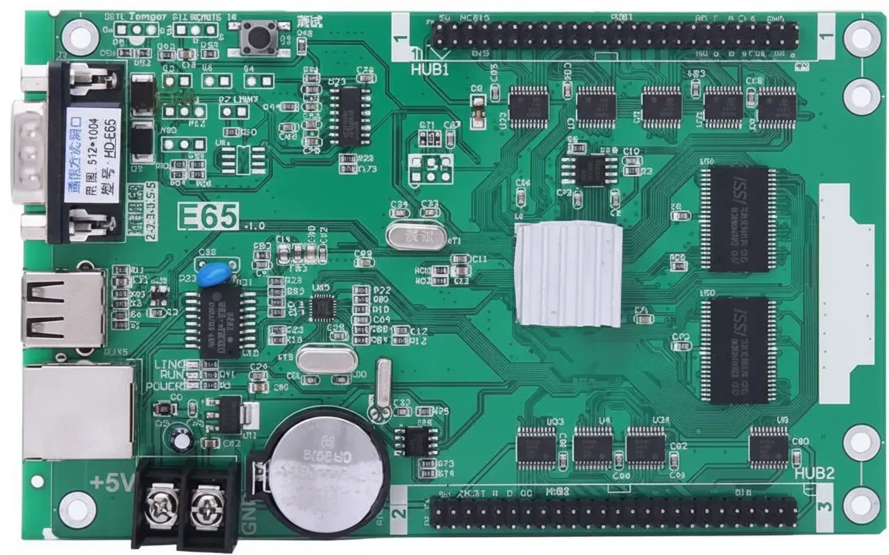
Across all LED circuit types, thermal vias, copper pours, and appropriate surface finishes (ENIG or OSP) ensure low contact resistance and long-term reliability. High-voltage sections incorporate slotting or increased spacing during fabrication to meet safety certifications. Aivon's controlled-impedance and high-Tg manufacturing processes guarantee repeatable performance whether the board is a simple night-light module or a complex multi-string driver backplane for large displays.
Conclusion
Effective LED driver circuit design ultimately hinges on robust PCB engineering that addresses current regulation, thermal management, high-voltage safety, and precise digital control. By applying disciplined layout techniques, appropriate material selection, and advanced manufacturing processes, engineers can deliver efficient, safe, and long-lasting LED lighting solutions across residential, commercial, and industrial applications. Aivon’s expertise in thermal, high-voltage, and multilayer PCB fabrication provides the reliable foundation required for next-generation LED systems.