Overview
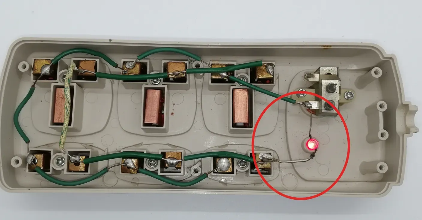
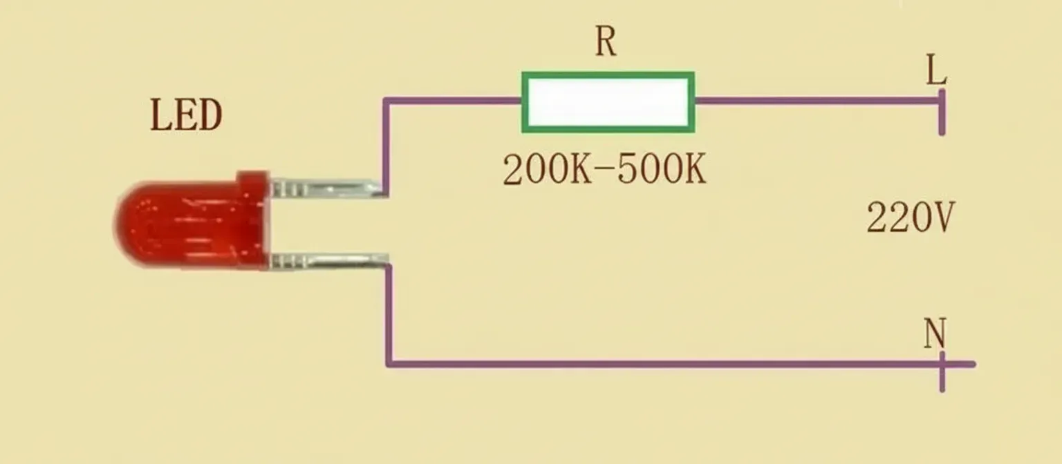
The simplest, lowest-cost way to connect a light-emitting diode (LED) to 220 V AC is to place a large series resistor, typically on the order of 200 kΩ to 500 kΩ. This approach is commonly used for indicator lights in power strips where cost is a primary constraint.
Considerations on LED Reverse Voltage and Current
Red LEDs can handle forward currents around 15 mA, but their reverse breakdown voltage is relatively low, generally only a few tens of volts. To prevent LED failure from excessive reverse voltage, the series resistor must be large enough so that its impedance under operating conditions is comparable to the LED's reverse impedance. In practice, using a sufficiently large series resistor significantly improves LED lifetime.
A straightforward calculation for continuous 15 mA operation is R = (220 V - 2 V) / 15 mA ≈ 14.7 kΩ. However, connecting an LED with only a 14.7 kΩ resistor directly to 220 V AC will typically destroy the LED due to the high reverse voltage during the AC negative half-cycle. To ensure reliable operation, the working current is usually reduced to well below 15 mA, often to around 1 mA or less, which requires much larger series resistance.
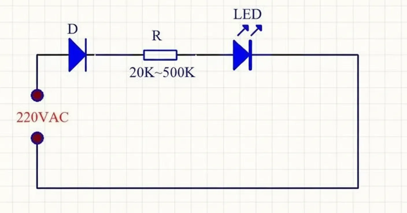
Series with a Rectifier Diode
Adding a rectifier diode in series with the LED blocks the LED from experiencing the full reverse voltage during the opposite half-cycle. With a series rectifier diode such as 1N4007, the minimum series resistor for 15 mA operation can be reduced. Considering the AC peak value: 220 V × 1.414 ≈ 311 V, then 311 V / 15 mA ≈ 20 kΩ. A series diode therefore allows a smaller resistor and a brighter LED compared with using only a large resistor, because the diode clamps the reverse voltage seen by the LED.
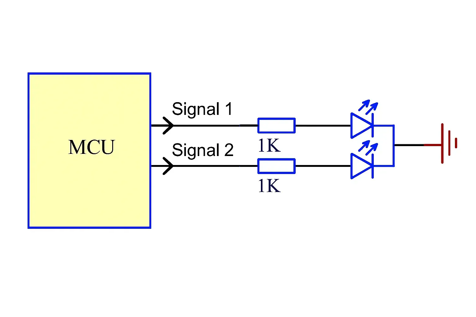
Anti-Parallel (Opposite-Polarity) LEDs
Connecting two LEDs in anti-parallel allows each LED to conduct on alternate half-cycles of the AC waveform: LED1 lights on the positive half-cycle and LED2 lights on the negative half-cycle. This configuration reduces the reverse voltage stress experienced by each LED because each conducts in its forward direction during its respective half-cycle. In practice, the series resistor can be smaller than with a single LED-only arrangement; values around 50 kΩ are commonly cited as a safe minimum depending on LED type and desired brightness. To avoid damage from voltage surges, do not operate LEDs at their absolute maximum rated forward current. If brightness is not critical, increasing the series resistance will extend LED lifetime.