A "chip" is the heart of electronic instruments. From satellites to smartphones such as the iPhone, and from complex CPUs to simple logic gates, circuit functions and control are implemented on chips.
Test and measurement instruments are no exception. As a measure of instrument performance, a test instrument must cover the device under test's operating frequency band, and measurement accuracy typically needs to exceed the device requirements by at least two units.
Keysight develops and integrates high-performance ASICs in its test instruments. These in-house chips are manufactured and tested by Keysight's chip team and are used across its measurement products. In later installments we will examine these instrument "chips" in more detail.
PNA-X overview
The PNA-X series microwave network analyzers are the result of more than 40 years of RF network analyzer technology and product development. The PNA-X functions as a vector network analyzer (VNA) and, for measurements of amplifiers, mixers, and frequency converters, acts as a high-integration, flexible microwave test engine.
Measurement capabilities
In common RF measurement scenarios—measuring coaxial devices directly, using test fixtures, or probing devices on wafers—the PNA-X combines fast measurement speed, high measurement accuracy, and an accessible user interface. Typical application areas include:
- S-parameters (continuous wave and pulsed)
- Noise figure
- Gain compression
- Intermodulation and harmonic distortion
- Frequency-conversion gain/loss
- True differential stimulation
- Nonlinear waveforms and X-parameter characterization
- Antenna testing
Internal components and MMIC examples
Inside the PNA-X are RF and microwave building blocks implemented as MMICs and other microwave subassemblies. Below are images from internal boards and modules.
Do you recognize familiar circuit topologies?
For example, the following are typical single-ended amplifiers used in RF and microwave signal chains. These amplifiers can operate up to 50 GHz and are designed as broadband amplifiers from DC to 50 GHz.
Frequency options and MMIC layout
The PNA-X mainframe offers high-frequency options up to 67 GHz. Ka-band options include 50 GHz or 43.5 GHz. Lower Ka options such as a 26.5 GHz VNA are also available; the 26.5 GHz amplifier below illustrates MMIC routing techniques used for high-frequency layout.
Millimeter-wave and terahertz extensions
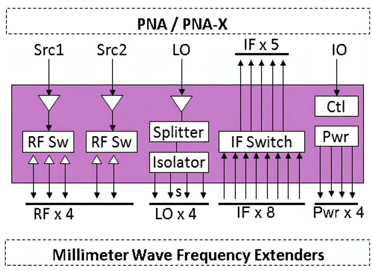
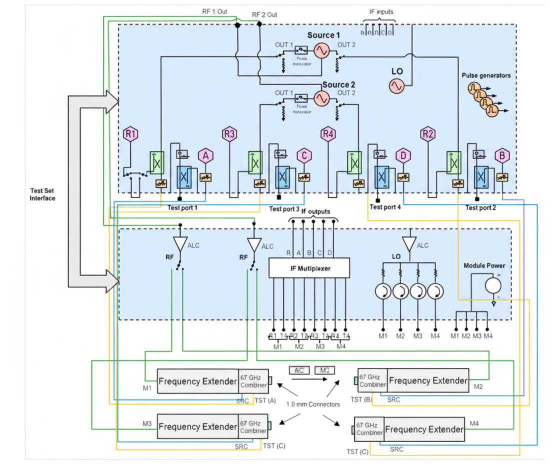
Millimeter-wave and terahertz are active research areas. Extending measurements into these bands requires VNAs with millimeter-wave range or external extension modules. The system architecture typically combines a high-frequency VNA with extension modules that expand the overall frequency coverage. The 110 GHz band is now available for use in the Chinese market, and systems reaching this band are realized by adding high-frequency extension modules to the VNA.
When extension modules are attached, the VNA is still operated from the mainframe interface. The analyzer automatically selects internal circuitry or external high-frequency modules depending on the working frequency. The extension approach typically extracts the intermediate frequency (IF) and local oscillator (LO) signals from inside the analyzer and uses harmonic mixing to translate the stimulus up to the W-band.
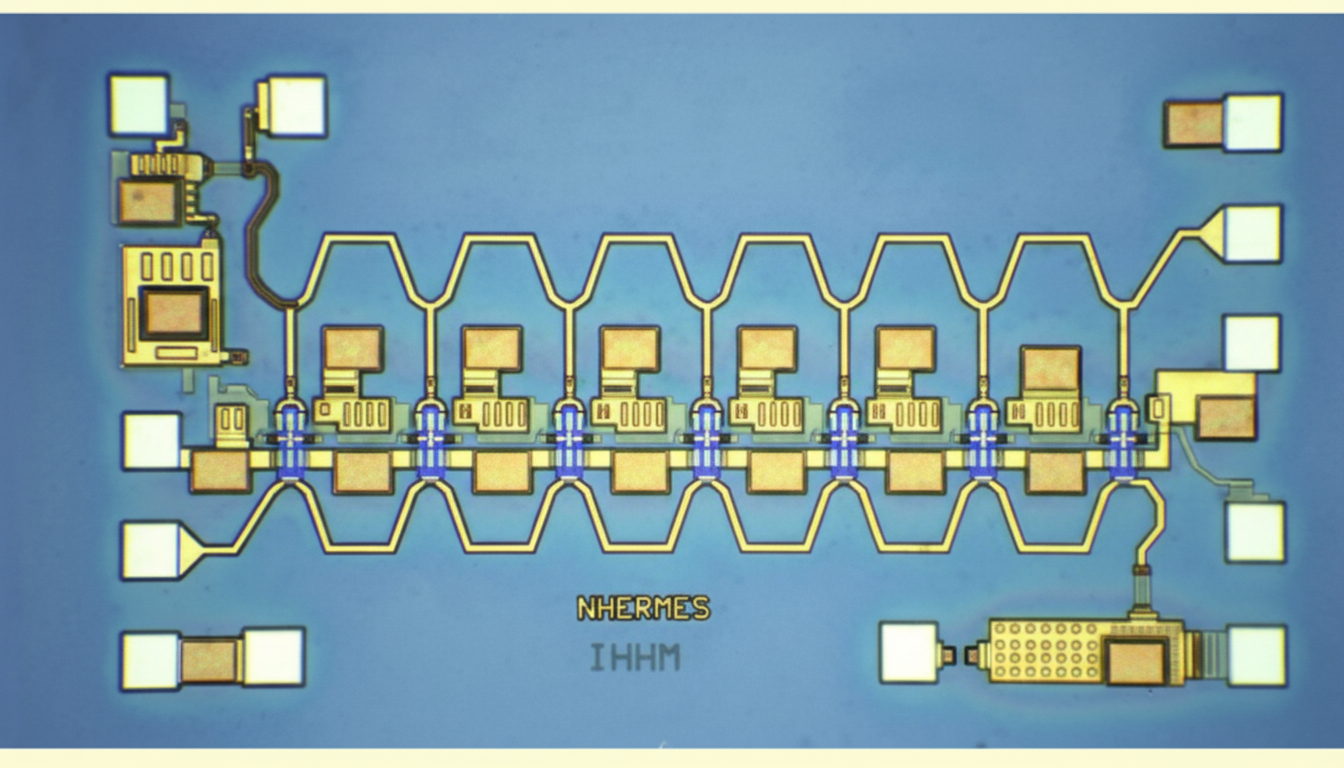
Controller and microwave switching
For precision, low-loss performance, the controller and microwave switching networks are key subcomponents. The images below show control assemblies and a millimeter-wave switch. The block in the upper-left of the board is a 75 GHz millimeter-wave switch; the three adjacent signal points form a typical switch topology used to route signals.