3D vision imaging enables robots and automated systems to perceive spatial information. Optical methods dominate industrial and robotic applications because they deliver non-contact measurement with high spatial resolution. Representative techniques include time-of-flight (TOF), scanning ranging, structured light projection, deflection-based methods for specular surfaces, stereo vision, and light-field imaging. Each approach imposes distinct requirements on sensor electronics, signal processing, and system integration.
Active Ranging Methods
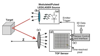
Time-of-flight (TOF) cameras measure depth by recording the round-trip travel time of light. Direct TOF (D-TOF) uses precise electronic timing of emitted pulses and reflected echoes, while indirect TOF (I-TOF) infers distance from time-gated intensity or phase measurements. I-TOF implementations are more practical at the pixel level because they avoid sub-nanosecond timing circuitry. TOF systems offer large fields of view, long working distances, and low cost, but they deliver moderate depth precision and remain sensitive to ambient light and multi-path reflections.
Scanning methods achieve higher precision through mechanical or optical beam steering. Single-point TOF, laser interferometry, and dispersive confocal techniques scan the surface sequentially. Active triangulation projects collimated laser lines or points and reconstructs geometry from the observed displacement on a camera. Dispersive confocal sensors provide absolute ranging on both rough and specular surfaces and are widely used for transparent cover-glass inspection. These methods require stable laser sources, precise beam delivery optics, and high-speed photodetection electronics.
Structured Light Projection
Structured light systems project known patterns onto a scene and reconstruct depth from the deformation captured by one or more cameras. Projectors based on DLP/DMD, LCD, or laser/LED sources support single-shot or multi-shot operation. Single-shot encodings (random dots, color or geometric multiplexing) enable fast acquisition, while multi-shot Gray-code and phase-shift sequences deliver higher accuracy at the expense of longer capture times. The projector can be treated as a virtual camera, turning the system into a calibrated triangulation setup. Reliable stripe indexing in multi-line configurations and handling of occlusions remain key engineering challenges.
Deflection-Based and Passive Methods
For highly reflective or specular surfaces, direct pattern projection produces glare. Deflection techniques project patterns onto a scattering screen or LCD and capture the reflected modulation from the specular surface, allowing curvature recovery without direct illumination.
Stereo vision reconstructs depth from disparity between images captured from different viewpoints. Binocular and multi-view setups require textured surfaces for reliable feature matching, while structure-from-motion (SfM) recovers both scene geometry and camera poses from sequential images. Light-field cameras insert a microlens array in front of the sensor to capture directional ray information, enabling post-capture refocusing and depth estimation in a single exposure.
Performance Comparison and Selection Criteria
TOF and light-field cameras provide compact, real-time single-unit solutions suitable for eye-in-hand robotic guidance, yet they currently offer limited spatial resolution or industrial-grade availability at moderate cost. Structured light and active triangulation deliver balanced precision and cost for many robotic tasks. Passive stereo vision is texture-dependent and requires sufficient baseline separation, which increases system size and creates occlusion risks. Multi-camera or multi-projector configurations mitigate shadows but add complexity and reduce flexibility for compact end-effector mounting.
Design and Manufacturing Considerations
Each 3D vision technique introduces specific electronic and optoelectronic constraints. TOF pixel arrays demand low-jitter clock distribution, precise analog front-ends, and high-speed data interfaces. Structured light projectors require stable LED or laser drive circuits, DMD control electronics, and synchronization with camera shutters. Scanning systems need galvanometer or MEMS mirror drivers with accurate position feedback. All approaches benefit from low-noise power delivery, electromagnetic shielding, and thermal management to maintain optical and electronic stability under industrial temperature and vibration conditions.
Environmental qualification (vibration, thermal cycling, ingress protection) directly influences component selection and PCB layout practices.
Industry Trends and System Integration
Robotic automation, collaborative robots, and autonomous mobile platforms continue to drive demand for compact, moderate-precision 3D vision with real-time performance. Integration with edge AI processors, high-speed interfaces (MIPI, GigE Vision, USB3 Vision), and multi-sensor fusion increases the complexity of the supporting electronics. These trends emphasize design-for-manufacturability practices that balance optical performance, electronic signal integrity, and mechanical robustness.
PCB and Electronic Manufacturing Relevance
Advanced PCB and flexible circuit technologies are essential enablers for 3D vision systems. High-speed image sensor interfaces require controlled-impedance routing, low-loss dielectrics, and precise via structures. Projector and laser driver circuits benefit from robust power planes and EMI suppression techniques. Flexible PCBs (FPC) support compact, vibration-resistant camera and illumination modules that conform to robotic arm geometries. High-density interconnect (HDI) and metal-core substrates provide thermal solutions for high-power LED PCBs and processors. Material selection for substrates, surface finishes, and conformal coatings directly affects long-term reliability in harsh industrial environments. Manufacturing processes such as fine-line etching, laser drilling, and automated optical inspection parallel the precision requirements of MEMS and semiconductor fabrication used in vision sensors.
These capabilities allow electronics suppliers to deliver reliable camera modules, projector boards, and integrated sensor assemblies that meet the stringent performance and environmental standards of modern robotic vision systems.
Conclusion
3D vision imaging encompasses a range of optical principles—active ranging, structured illumination, and passive disparity—each with distinct accuracy, speed, cost, and integration trade-offs. Realizing these methods in practical robotic and industrial systems depends on precise optoelectronic design, signal integrity, and environmental resilience. PCB fabrication, assembly, and material engineering practices underpin the sensor interfaces, processing electronics, and interconnects required for dependable 3D vision performance across diverse applications.