MEMS gyroscopes measure angular velocity around one or more axes and have become standard components in smartphones, wearables, automotive systems, and industrial equipment. Unlike earlier mechanical gyroscopes used primarily in aerospace and maritime navigation, MEMS versions provide solid-state construction, low power consumption, and compatibility with high-volume semiconductor processes. They complement accelerometers to form inertial measurement units (IMUs) that support sensor fusion for accurate motion tracking, navigation, and stabilization.
Operating Principle and Sensing Mechanism
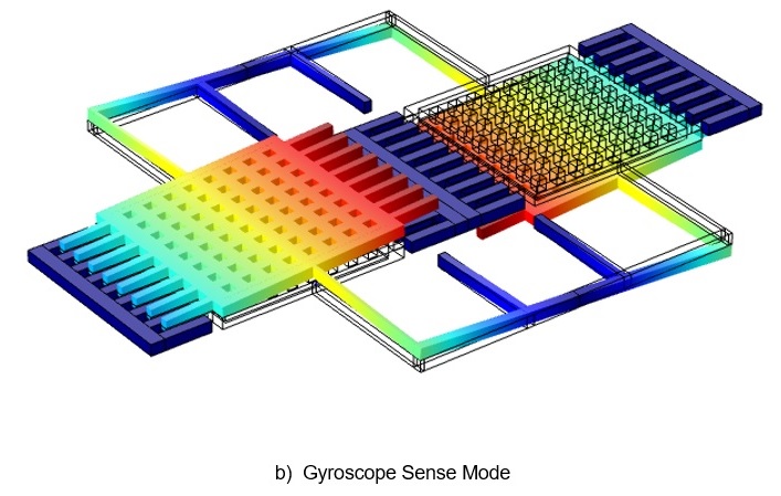
Most consumer and industrial MEMS gyroscopes rely on a micromachined tuning-fork structure driven into resonance. Two proof masses oscillate in anti-phase. An external angular rate about the sensing axis generates a Coriolis force perpendicular to the drive motion, producing a proportional displacement. This displacement modulates the capacitance between the moving rotor and fixed stator electrodes. Dedicated ASIC circuitry converts the capacitance variation into an analog or digital output proportional to angular rate. Differential sensing cancels common-mode signals from linear acceleration or vibration, improving immunity to external disturbances.
System Architecture and Signal Chain
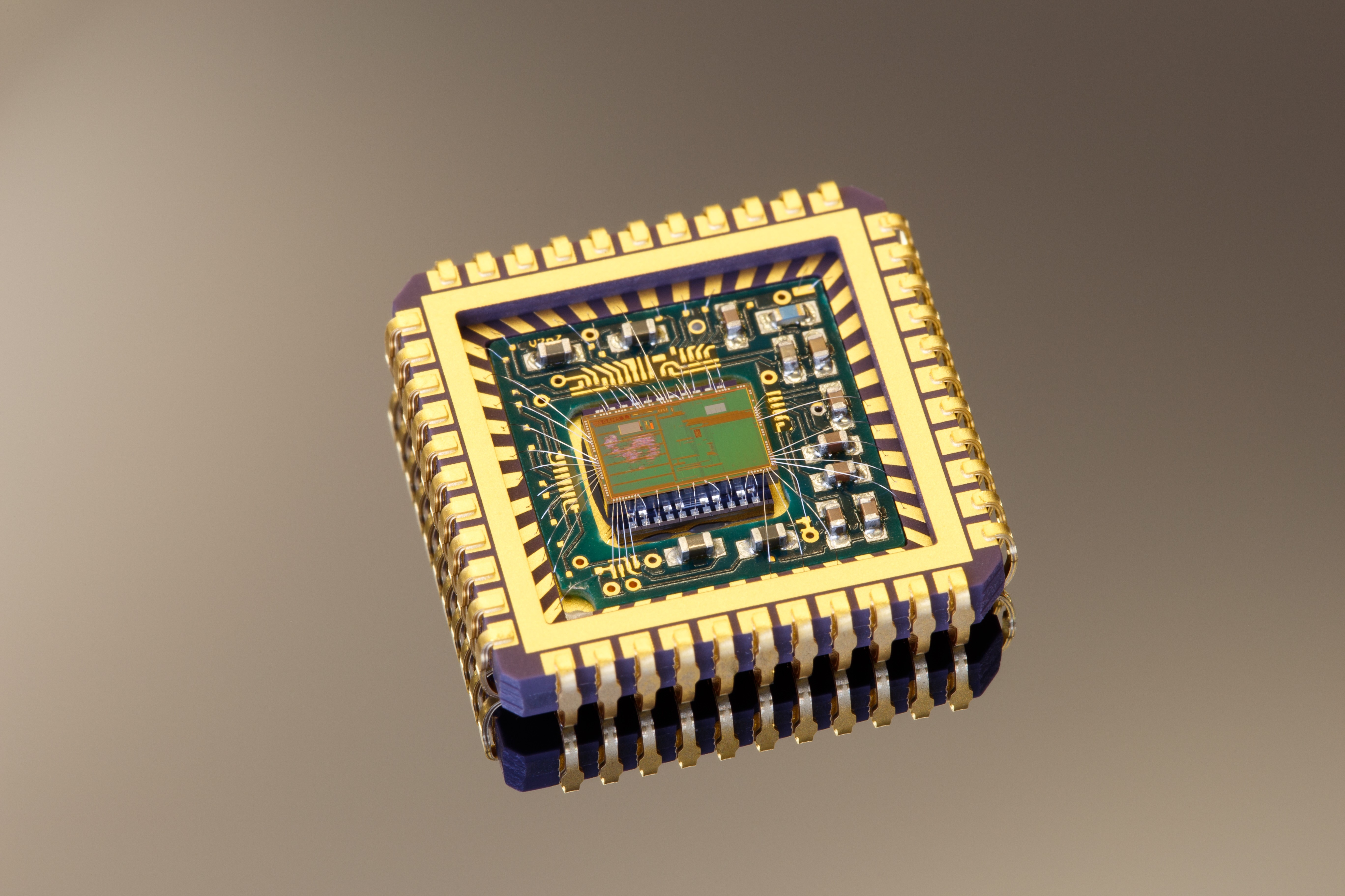
A typical MEMS gyroscope divides into a drive loop that electrostatically maintains oscillation and a sense loop that detects Coriolis-induced motion. Many devices integrate the mechanical sensor element and signal-conditioning ASIC in a single system-in-package (SiP). Advanced packaging achieves footprints of a few millimeters on each side with sub-millimeter thickness. Digital interfaces such as I²C or SPI, on-chip temperature compensation, FIFO buffering, and configurable low-pass filtering simplify board-level implementation. Power-management modes, including shutdown and sleep, support battery-constrained applications.
Applications in Electronics and Broader Markets
In consumer devices, gyroscopes improve image stabilization in cameras, enable precise gesture recognition and gaming controls, and enhance dead-reckoning when GPS signals are unavailable. Combined with accelerometers and magnetometers, they deliver orientation data for augmented reality and indoor navigation. Automotive uses include electronic stability control, rollover detection, and advanced driver-assistance systems. Industrial and medical equipment employ them for robotic motion control, platform stabilization, and patient monitoring. Measurement ranges typically span tens to several thousand degrees per second, with automotive-grade parts qualified to AEC-Q100 and capable of withstanding 10,000 g shocks.
Design Considerations for PCB and FPC Integration
Successful board-level integration requires attention to mechanical mounting, thermal expansion mismatch between silicon and substrate materials, and electromagnetic compatibility. Controlled-impedance routing and proper grounding minimize noise coupling into the sensitive capacitance interface. For flexible printed circuits (FPCs), the sensor package must accommodate repeated bending without inducing stress on wire bonds or solder joints. Multi-axis devices benefit from symmetric layout to reduce cross-axis sensitivity. Power-supply decoupling and temperature-gradient management across the board help maintain zero-rate offset stability.
Manufacturing and Reliability Challenges
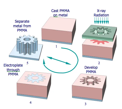
MEMS fabrication involves deep reactive-ion etching of silicon wafers to create high-aspect-ratio structures, followed by wafer-level capping for hermetic sealing. High-volume production demands tight control of film stress, etch uniformity, and release processes to achieve consistent resonance frequency and quality factor. Post-assembly challenges include solder reflow effects on package stress, moisture ingress, and long-term drift under temperature cycling or vibration. Qualification testing typically covers temperature-humidity-bias, thermal shock, mechanical shock, and vibration per automotive or industrial standards. Scalability requires suppliers to maintain process capability indices that support yields above 99 % while meeting cost targets for consumer volumes.
Industry Trends in Inertial Sensing
Demand continues to grow for smaller, lower-power, and higher-performance inertial sensors that support sensor fusion in edge AI devices and autonomous systems. Integration of gyroscopes with additional modalities such as pressure or magnetic sensing reduces overall system size. Advances in wafer-level packaging and through-silicon vias enable thinner profiles suitable for foldable electronics and wearable form factors. Reliability requirements are increasing in automotive and industrial IoT applications, driving development of self-test features and on-chip diagnostics.
PCB and Electronics Manufacturing Perspective
PCB and FPC manufacturers address inertial-sensor integration through precise surface-mount placement, controlled reflow profiles, and underfill or conformal coating where vibration resistance is critical. High-density interconnect (HDI) technology supports compact layouts for multi-sensor modules, while flexible substrates enable three-dimensional placement inside enclosures. Material selection for laminates considers coefficient of thermal expansion compatibility and low dielectric loss at high frequencies when RF circuits coexist with motion sensors. Reliability engineering includes accelerated life testing and failure-mode analysis specific to MEMS packages. These capabilities allow electronics manufacturers to qualify complete assemblies that maintain angular-rate accuracy across operating environments and product lifetimes.
FAQs
Q1: How does a MEMS gyroscope convert angular rate into an electrical signal?
A1: A resonating tuning-fork structure experiences Coriolis force under rotation; the resulting displacement changes electrode capacitance, which is measured and converted to a rate-proportional output by the ASIC.
Q2: What PCB layout practices improve MEMS gyroscope performance?
A2: Symmetric placement, adequate decoupling, controlled-impedance traces, and attention to thermal gradients help maintain offset stability and reduce noise.
Q3: Are MEMS gyroscopes suitable for flexible circuit applications?
A3: Yes, when packaged appropriately and mounted with strain-relief features, they support repeated bending while preserving sensing accuracy.