Magnetic and optical encoders are widely used sensors for measuring angular position, speed, and linear displacement in motion control systems. Although both convert mechanical motion into electrical signals, they rely on fundamentally different physical principles and impose distinct requirements on associated electronic hardware.
Operating Principles
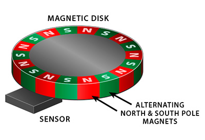
Magnetic encoders utilize the magnetoresistive effect. A magnetic drum or ring is magnetized with alternating poles at precise intervals. As the drum rotates, the changing magnetic field alters the resistance of magnetoresistive sensors. When biased by a supply voltage, these resistance changes generate analog voltage signals that are conditioned and digitized by downstream electronics for controller interpretation.
Optical encoders operate on light interruption or reflection. A code disk patterned with alternating transparent and opaque segments rotates between a light source (typically an LED) and an optical receiver (photodiodes or phototransistors). The resulting modulated light produces pulse trains that indicate position or direction after appropriate signal processing.
Traditional code disk substrates include glass for high line density and thermal stability, metal for durability, and plastic for cost-sensitive or lightweight designs. Glass disks deliver superior accuracy but remain susceptible to mechanical shock.

Performance Characteristics and Trade-offs
Magnetic encoders provide strong immunity to electromagnetic interference, vibration, dust, and contamination. They operate reliably across wide temperature ranges and do not require precise optical alignment, simplifying installation in harsh industrial environments.
Optical encoders achieve compact form factors and can support high rotational speeds with relatively simple signal processing. They remain unaffected by external magnetic fields and benefit from mature, cost-effective manufacturing processes for many standard applications. However, they are more sensitive to contamination, misalignment, and mechanical shock when glass disks are employed.
Selection between the two technologies depends on environmental conditions, required resolution, speed, space constraints, and cost targets. Magnetic encoders are often preferred in heavy-industry or contaminated settings, while optical encoders suit clean, space-limited, or high-speed applications.
Design and Manufacturing Considerations
Encoder integration introduces several engineering constraints. Magnetic sensor modules require stable biasing circuitry and low-noise analog front-ends on the PCB to preserve signal integrity from weak magnetoresistive outputs. Radar-like EMI susceptibility in adjacent systems necessitates careful grounding, shielding, and trace routing.
Optical encoder electronics demand high-speed pulse detection, precise LED drive current control, and robust digital interfaces. Photodiode arrays and associated transimpedance amplifiers benefit from low-leakage PCB materials and controlled-impedance routing to maintain edge timing accuracy at high speeds.
Both encoder types must endure automotive or industrial qualification testing, including vibration, thermal cycling, humidity, and ingress protection. These requirements influence substrate selection, conformal coating application, and component packaging choices.
Materials and PCB/FPC Relevance
Encoder performance and longevity depend heavily on PCB design and material selection. Low-loss dielectrics and controlled copper thickness support clean analog signal paths in magnetic encoders. High-speed digital layers with proper impedance control are essential for optical pulse trains. Flexible PCBs enable compact, vibration-resistant encoder assemblies that conform to curved housings or rotating shafts.
High-density interconnect (HDI) techniques allow miniaturization of multi-channel encoder interfaces while maintaining signal integrity. Thermal management considerations, such as copper-core PCBs or embedded copper planes, help stabilize LED output or sensor bias points under varying ambient conditions. Material engineering choices—glass versus metal code disks, FR-4 versus polyimide substrates—directly affect long-term reliability in demanding applications.
Industry Trends and System Integration
The proliferation of servo motors, robotics, and automated machinery continues to increase demand for encoders with higher resolution, faster response, and greater environmental robustness. Integration with fieldbus or Ethernet interfaces adds requirements for galvanic isolation and high-speed transceivers on the same PCB assembly. These trends emphasize design-for-manufacturability practices that balance performance, size, and production scalability.
PCB and Electronic Manufacturing Relevance
PCB fabrication and assembly processes are critical enablers for both magnetic and optical encoder performance. Precise control of dielectric constants, via structures, and surface finishes ensures the signal fidelity required by magnetoresistive sensors and optical receivers. Flexible circuit constructions support compact, mechanically robust encoder modules, while rigorous testing and quality controls verify operation across specified temperature, vibration, and contamination ranges. These manufacturing capabilities allow electronics suppliers to deliver encoder interface boards and integrated sensor assemblies that meet the stringent reliability demands of industrial motion control systems.
Conclusion
Magnetic and optical encoders each address specific measurement needs through distinct physical mechanisms, yet both ultimately rely on precise electronic signal conditioning and robust hardware integration. Magnetoresistive and optical detection paths place clear demands on PCB layout, material properties, and assembly processes to achieve the noise immunity, timing accuracy, and environmental resilience required in real-world applications. As motion control systems evolve toward higher precision and greater integration, the ability to produce application-specific PCBs, flexible circuits, and high-reliability encoder electronics remains essential for dependable system performance.