Magnetic-based speed sensors convert rotational motion into electrical pulse trains using electromagnetic effects. They operate in non-contact mode and are classified as active or passive depending on whether an external magnetic bias is required. The primary technologies include Hall-effect, magnetoresistive, and eddy-current sensors. These devices are deployed in power generation, automotive, aerospace, textile, and petrochemical equipment to monitor shaft speed for closed-loop control and condition monitoring.
Basic Measurement Principles
Both active and passive magnetic sensors detect periodic changes in magnetic flux caused by a rotating target featuring teeth, slots, or embedded magnets. As the target rotates, the varying flux induces periodic voltage or resistance changes that are conditioned into digital pulses. Pulse frequency is directly proportional to rotational speed. Hall sensors typically require a magnetic element on the rotating object, while magnetoresistive and eddy-current sensors respond to the changing reluctance or eddy currents produced by a ferromagnetic gear or wheel.
Hall-Effect Speed Sensors
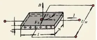
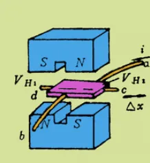
A Hall element placed in a magnetic field and biased with constant current produces a transverse voltage (Hall voltage) proportional to the perpendicular component of magnetic flux density. With fixed bias current and element thickness, output voltage varies linearly with flux density. Integrated Hall switches and linear sensors combine the sensing element with amplification and signal conditioning on a single die.
Key characteristics of the hall-effect sensor include static magnetic sensitivity, small size, low noise, wide bandwidth (DC to several megahertz), large dynamic range, and long operational life. Selection considerations for speed applications include sensitivity, temperature coefficient, and output configuration. Indium antimonide elements are often chosen for high sensitivity in pulse detection, while gallium arsenide elements provide better temperature stability for precision measurements.
Magnetoresistive Speed Sensors
Magnetoresistive sensors exploit the change in resistance of a semiconductor or thin-film element when exposed to a magnetic field (Gauss effect). Unlike the Hall effect, the resistance change occurs parallel to the current flow. Elements are commonly configured in a Wheatstone bridge to produce a differential voltage proportional to the field variation. Higher carrier mobility and lower length-to-width ratios increase sensitivity. These sensors offer good linearity and are suitable for detecting small flux changes produced by rotating ferromagnetic targets.
Eddy-Current Speed Sensors
Eddy-current sensors induce alternating currents in a conductive or ferromagnetic target. The resulting opposing magnetic field alters the impedance of the sensing coil. Periodic changes in coil impedance as teeth or notches pass the probe are converted to voltage pulses. This principle provides robust performance in harsh environments with oil, dust, or vibration.
Applications in Industrial and Automotive Systems
Magnetic speed sensors support closed-loop motor control, turbine monitoring, wheel-speed measurement for ABS and traction control, crankshaft and camshaft position sensing, and process equipment speed regulation. They provide reliable output even when the target is stationary (zero-speed detection with certain Hall and magnetoresistive designs) and operate across wide temperature and contamination ranges.
Design Constraints and Reliability Considerations
Sensor performance depends on air-gap tolerance, target geometry (tooth size, spacing, material permeability), and alignment. Excessive gap reduces signal amplitude; misalignment introduces phase errors. Temperature-induced drift in Hall voltage or magnetoresistive coefficient must be compensated through circuit design or software calibration. Electromagnetic interference from nearby motors or power electronics can couple into the sensor output, requiring shielding and filtering.
Reliability testing includes thermal cycling, vibration, humidity exposure, and accelerated life testing to verify long-term pulse integrity and offset stability. Calibration traceability to national standards is essential for metrology applications.
PCB Layout, Materials, and Electronic Integration
Speed sensor modules interface with control electronics through analog or digital outputs that demand careful PCB design. Analog Hall or magnetoresistive signals are susceptible to noise; therefore, layout practices include short trace lengths, proper grounding planes, and separation of sensor power from digital switching currents. Controlled-impedance routing supports high-frequency pulse transmission when the sensor is located remotely from the processor.
Low-loss laminates and appropriate copper weights help maintain signal integrity and thermal stability. Flexible printed circuits (FPCs) enable compact integration in rotating or space-constrained assemblies while preserving mechanical flexibility. High-density interconnect HDI technology supports miniaturization when multiple sensors or signal-conditioning ICs share a board. Thermal vias and copper balancing dissipate heat from onboard amplifiers or microcontrollers. Material selection for substrates, solder masks, and conformal coatings must consider temperature range, vibration resistance, and electromagnetic compatibility.
Manufacturing processes for the complete module include precise sensor placement, wire bonding or connector attachment, and functional testing of pulse output under simulated rotation. Electrical and environmental qualification verifies that the assembled sensor meets accuracy and reliability specifications before volume production.
Industry Trends
Integration of magnetic sensors with on-chip signal conditioning and digital interfaces (I2C, SPI, SENT) continues to reduce external component count. Advances in thin-film magnetoresistive materials and MEMS-based Hall elements improve sensitivity and temperature performance. Electromagnetic compatibility requirements and functional safety standards (ISO 26262 in automotive) drive increased attention to sensor diagnostics and redundancy.
Electronic Manufacturing and PCB Technologies Supporting Magnetic Speed Sensor Systems
Magnetic speed sensor modules depend on multilayer PCBs with controlled-impedance traces and mixed-signal partitioning to preserve low-noise analog signals from the sensing element through the digital interface. Fabrication processes that deliver consistent dielectric properties and fine-feature copper enable reliable high-speed pulse transmission. Assembly techniques, including precise sensor alignment, thermal management, and robust encapsulation, support the transition from prototype to volume production while maintaining electromagnetic compatibility and long-term reliability. These manufacturing considerations directly influence measurement accuracy, system uptime, and field performance in demanding industrial environments.
Conclusion
Magnetic-based speed sensors provide robust, non-contact rotational measurement through well-established electromagnetic principles. Effective system integration requires coordinated sensor selection, signal conditioning, and printed circuit board design to maintain accuracy under real-world environmental stresses. Manufacturing processes that ensure consistent material properties, tight mechanical tolerances, and thorough reliability testing are fundamental to achieving repeatable performance in industrial and automotive applications.