Temperature sensors enable precise thermal monitoring in automotive electronics, industrial controls, household appliances, and process equipment. Selecting the appropriate sensor type requires evaluating measurement range, accuracy, response time, excitation requirements, and compatibility with printed circuit board (PCB) assembly and signal conditioning.
The four primary sensor technologies are thermocouples, thermistors (NTC and PTC), resistance temperature detectors (RTDs), and chip-based integrated-circuit (IC) sensors. Each presents distinct trade-offs in performance, interface complexity, and manufacturing integration.
Thermocouples
Thermocouples generate a voltage proportional to temperature difference between the measurement junction and a reference point. They require no excitation current, operate from cryogenic temperatures to approximately 2000 °C, and exhibit fast thermal response.
The output voltage is small—approximately 40 µV/°C for a Type K device—necessitating high-resolution amplification and careful noise management, particularly when long traces or cables connect the sensor to the measurement circuitry. Cold-junction compensation is mandatory because the connection to copper PCB traces forms an unintended second thermocouple. Compensation typically involves placing a local temperature sensor at the termination point and applying the correction:
V_tc = V_out + V_cj
where V_tc is the compensated thermocouple voltage and V_cj is the cold-junction contribution.
PCB considerations: Minimize thermoelectric voltages by using matched copper traces or isothermal terminal blocks. Route signals differentially and shield against electromagnetic interference. In high-volume assembly, automated placement of compensation sensors and controlled soldering profiles help maintain junction integrity.
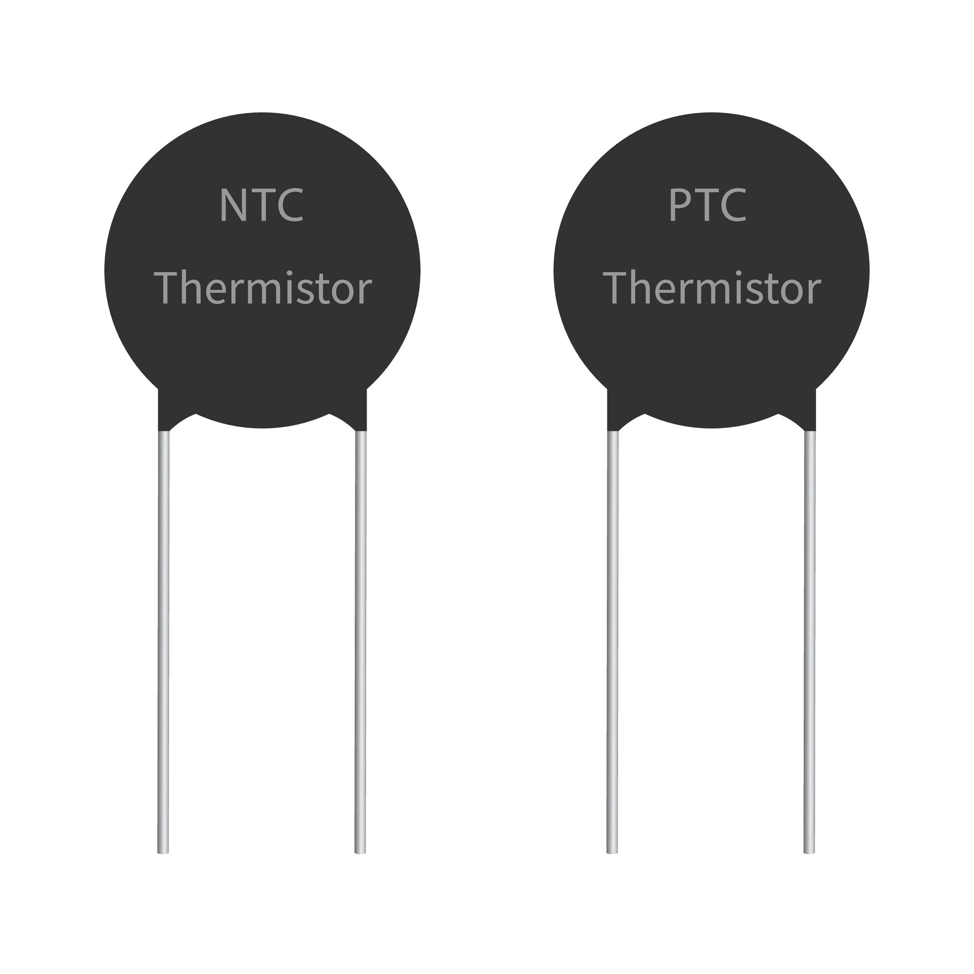
Thermistors (NTC and PTC)
Thermistors are temperature-dependent resistors. NTC devices exhibit decreasing resistance with rising temperature; PTC devices show increasing resistance, often with a sharp transition at a switching temperature.
NTC thermistors provide high sensitivity and are commonly applied in temperature compensation of crystal oscillators, inrush-current limiting, and closed-loop control. Their resistance-temperature characteristic is nonlinear but can be linearized over limited ranges. Key parameters include the B constant (calculated from resistance at two temperatures), thermal time constant, and voltage-withstand rating.
PTC thermistors serve primarily as self-resetting overcurrent protectors and heater controls, where resistance increases by orders of magnitude above the Curie point.
| Type | Description |
|---|---|
| PTC | Positive temperature coefficient — resistance increases with temperature |
| NTC | Negative temperature coefficient — resistance decreases with temperature |
PCB considerations: Self-heating from measurement current must be limited; typical excitation is kept below 1 mA. Thermal time constant is influenced by PCB copper pour, component encapsulation, and airflow. Accurate placement away from heat-generating components (power transistors, regulators) improves measurement fidelity. Automated optical inspection verifies solder joint quality to avoid resistance drift from poor contacts.
Resistance Temperature Detectors (RTDs)
RTDs, most commonly platinum-based (Pt100, Pt1000), deliver near-linear resistance change with temperature and excellent long-term stability. Standard temperature coefficients follow DIN EN 60751, with the resistance approximated by:
R = R₀ (1 + A·t + B·t² + C·t³) for t < 0 °C
R = R₀ (1 + A·t) for t ≥ 0 °C
where R₀ is resistance at 0 °C and coefficients A, B, C are defined by the standard.
Wiring configurations directly affect accuracy on PCBs. Two-wire connections include lead resistance; three- and four-wire configurations eliminate this error by separating excitation and sense paths. Ratio measurement using a precision reference resistor and a sigma-delta ADC simplifies excitation accuracy requirements and enables effective 50/60 Hz rejection.
PCB considerations: Trace resistance and thermoelectric effects must be minimized. Four-wire Kelvin connections are preferred for Pt1000 sensors to maximize voltage swing at the ADC. Thermal gradients across the PCB can introduce errors; copper planes and component placement should be evaluated during layout review. Calibration at 0 °C and verification across the operating range ensure compliance with specified tolerance (e.g., ±0.15 % over −30 °C to 300 °C).
Chip-Based IC Temperature Sensors
IC sensors integrate the sensing element, signal conditioning, and often digital output (I²C, SPI) or analog voltage/current. They offer good accuracy (±0.5 °C to ±2 °C) within a moderate range (−55 °C to +150 °C typical), low power consumption, and straightforward PCB mounting.
PCB considerations: Minimal external components reduce bill-of-materials complexity. Thermal coupling to the die is achieved through the package; exposed-pad or thermal-via designs improve response. Digital interfaces simplify isolation from analog noise sources on mixed-signal boards.
Design and Manufacturing Implications for PCB Assembly
Sensor choice influences PCB layout, component selection, and test strategy. Thermocouples demand careful cold-junction placement and shielding. RTDs require low-resistance traces or dedicated sense lines. Thermistors need controlled excitation and thermal isolation. IC sensors benefit from standard reflow profiles but still require attention to package thermal resistance.
High-volume manufacturing benefits from designs that support automated test equipment, in-circuit verification of wiring configurations, and traceability of calibration data. Material selection for substrates (FR-4, polyimide for flexible circuits) and surface finishes affects long-term drift under thermal cycling and humidity.
Industry Applications and Trends
Automotive powertrain and battery management systems favor RTDs and NTC thermistors for wide temperature coverage and robustness. Industrial process control increasingly adopts digital IC sensors for simplified integration and diagnostics. High-reliability sectors emphasize four-wire RTDs and thermocouple compensation accuracy.
Emerging requirements include higher channel density on HDI PCBs, improved electromagnetic compatibility, and support for predictive maintenance through continuous temperature monitoring. Advances in sigma-delta ADCs with integrated excitation and diagnostic features reduce external component count while enhancing measurement integrity.
Supporting Reliable Temperature Measurement in Electronics Manufacturing
PCB fabrication and assembly processes directly influence sensor performance through trace geometry, via placement, solder joint quality, and thermal management features. Controlled impedance routing, proper grounding strategies, and thermal relief patterns help preserve the integrity of low-level signals from thermocouples and RTDs. Flexible printed circuits enable sensor placement in confined or moving assemblies while maintaining reliable interconnects. Rigorous incoming inspection, reflow profile optimization, and post-assembly electrical testing ensure that the chosen temperature-sensing architecture meets both functional and reliability specifications across the product lifecycle.
FAQs
Q1: Which sensor offers the widest temperature range?
A1: Thermocouples, extending up to approximately 2000 °C.
Q2: What wiring configuration eliminates lead resistance in RTD measurements?
A2: Three- or four-wire configurations.
Q3: How does PCB layout affect thermocouple accuracy?
A3: Cold-junction location, trace material matching, and electromagnetic shielding determine compensation accuracy and noise immunity.