Electronic compasses determine heading relative to the Earth's magnetic field using magnetoresistive, Hall-effect, or fluxgate sensors. They compensate for limitations of GPS-based navigation, such as signal blockage in urban canyons, tunnels, or indoor environments, and provide reliable orientation when the platform is stationary. A typical three-axis system measures the geomagnetic vector (approximately 0.3–0.6 Gauss) and applies tilt correction to maintain accuracy across a range of attitudes.
Geomagnetic Field Measurement and Tilt Compensation
The geomagnetic field is a vector with horizontal and vertical components that vary by location and time. When the sensor platform remains level, azimuth is computed directly from the X and Y magnetometer axes. Under tilt, pitch and roll angles measured by a dual-axis accelerometer are used to rotate the measured vector back to the horizontal plane using coordinate transformation equations. Onboard processing applies hard-iron and soft-iron calibration to remove local magnetic distortions.
Sensor Types and Performance Characteristics
Three primary sensor technologies are employed:
- Magnetoresistive (AMR) sensors offer high sensitivity and linearity suitable for weak-field measurement, with fast response times, though they can exhibit switching effects and require careful current management.
- Hall-effect sensors provide small size, low power consumption, and low cost but generally lower sensitivity and poorer temperature stability, limiting their use to applications with modest accuracy requirements.
- Fluxgate sensors achieve high resolution for weak magnetic fields through core saturation principles but are larger and slower than AMR-based solutions.
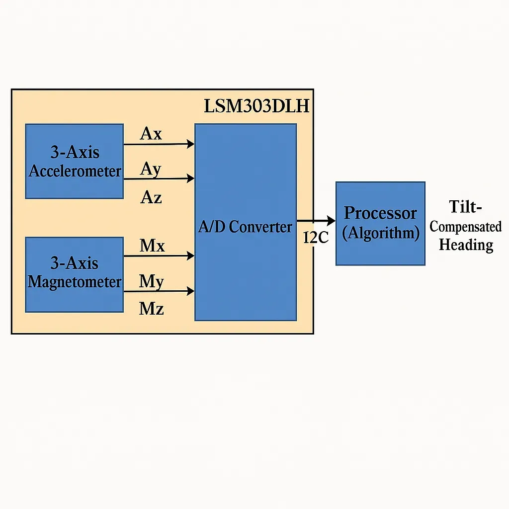
A complete module typically integrates a three-axis magnetometer, three-axis accelerometer, analog-to-digital conversion, temperature compensation, and a microcontroller communicating over I2C or SPI.
System Architecture and Data Processing
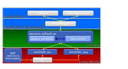
Raw magnetic and acceleration vectors are acquired, conditioned, and processed to produce heading and inclination outputs independent of device attitude. Software layers include kernel drivers for hardware access, hardware abstraction, framework management, and application interfaces that supply data to mapping, augmented reality, or navigation functions.
Applications in Navigation and Industrial Systems
Electronic compasses supplement GPS in automotive navigation, UAV flight control, robotics motion correction, marine and aviation heading reference, and intelligent parking detection. They enable map rotation aligned with user heading and provide absolute orientation references that counteract inertial drift in combined sensor fusion systems. In environments with strong local magnetic interference, gyroscope augmentation or careful sensor placement becomes necessary.
Design and Manufacturing Considerations
Integration of magnetic sensors demands low-noise analog front ends, stable reference voltages, and shielding to minimize interference from nearby digital circuitry or power traces. Calibration routines must be executed during manufacturing and may require periodic field recalibration. Environmental testing for temperature drift, vibration, and electromagnetic susceptibility ensures consistent performance across operating conditions.
PCB Layout and Material Selection
Printed circuit boards for electronic compass modules require careful partitioning of analog sensor sections from digital processing and power domains. Controlled-impedance routing, proper grounding schemes, and guard traces reduce noise coupling into sensitive magnetometer channels. Low-loss laminates and appropriate copper weights support stable power delivery and thermal performance. Flexible printed circuits (FPCs) enable compact or conformal mounting in wearable or automotive assemblies while maintaining signal integrity. Material choices such as polyimide substrates with low moisture absorption help preserve calibration stability under humidity and temperature cycling.
High-density interconnect (HDI) technology facilitates miniaturization when multiple sensors and microcontrollers share a single board. Thermal vias and balanced copper distribution mitigate localized heating that could affect sensor offset. Manufacturing processes must maintain tight tolerances on trace geometry and via quality to ensure repeatable electromagnetic performance. Reliability engineering includes accelerated life testing, magnetic calibration verification, and electromagnetic compatibility qualification before volume production.
Industry Trends
Advances in MEMS-based magnetometers and integrated sensor fusion algorithms continue to reduce module size and power consumption. Increased adoption in autonomous systems and IoT devices drives demand for higher accuracy under dynamic conditions and improved resistance to magnetic interference. Electromagnetic compatibility standards and calibration traceability remain important considerations in regulated markets.
Electronic Manufacturing and PCB Technologies Supporting Compass Systems
Compass modules rely on multilayer PCBs with mixed-signal partitioning and controlled-impedance traces to preserve weak magnetic signal integrity. Fabrication processes that deliver consistent dielectric properties and low-variation copper features support repeatable sensor performance. Assembly methods, including precise placement of magnetometers and accelerometers together with appropriate shielding and thermal management, ensure mechanical and electrical stability. These manufacturing considerations underpin reliable operation across automotive, aerospace, robotics, and consumer navigation applications.
Conclusion
Electronic compass performance depends on precise sensor selection, accurate tilt compensation, and robust electronic integration. Printed circuit board design and manufacturing processes directly influence noise performance, calibration stability, and long-term reliability. Attention to layout, material properties, and assembly techniques enables the transition from laboratory prototypes to production modules suitable for demanding navigation and industrial environments.