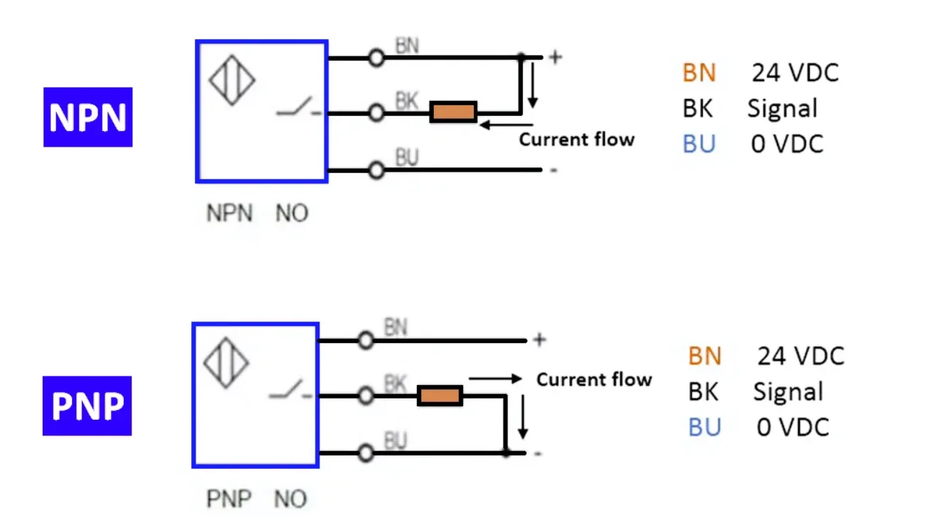
Three-wire proximity sensors (inductive, capacitive, ultrasonic, and photoelectric) are fundamental components in industrial automation. These solid-state devices use internal transistors to switch outputs when detecting objects, providing reliable digital signals to PLCs and control systems. The two primary output configurations-PNP and NPN-differ in transistor polarity and current flow direction.
Understanding these differences is essential for correct wiring, avoiding damage, and ensuring system compatibility.
PNP and NPN Sensor Fundamentals
PNP Sensors (Sourcing)
The output transistor connects the load to the positive supply. When activated, current flows from the sensor output to the load (sourcing current). Commonly used with sinking PLC inputs.
NPN Sensors (Sinking)
The output transistor connects the load to ground. When activated, current flows from the load through the sensor to negative (sinking current). Typically paired with sourcing PLC inputs.
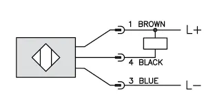
Both types are available in Normally Open (N/O) or Normally Closed (N/C) configurations, independent of the PNP/NPN polarity. Wire colors are standardized: brown (positive), blue (negative), and black (signal output).
Why Two Configurations Exist
PNP sensors are more common in many European systems and relay-based controls, while NPN types see frequent use in certain Asian markets. The choice depends on the PLC input module type:
- Sink (Current Sinking) Inputs: Common with PNP sensors.
- Source (Current Sourcing) Inputs: Compatible with NPN sensors.
Many modern PLC modules are configurable as sink or source, but consistency across the module is required. Always consult manufacturer documentation for specific wiring.
Practical Wiring Considerations
Typical 3-wire setup:
- Brown: +24VDC supply
- Blue: 0V (ground)
- Black: Signal output to PLC input
Key Practices:
- Match sensor output type to PLC input polarity.
- Use proper fusing and suppression (e.g., flyback diodes for inductive loads).
- Maintain short, shielded cables in noisy environments.
- Verify voltage levels and current ratings to prevent damage.
Dashed lines in standard diagrams often represent optional connections depending on the specific hardware.
PCB and Control Panel Integration
Reliable sensor interfaces benefit from thoughtful electronics design:
- I/O Conditioning Boards: Include isolation, filtering, and LED status indicators on dedicated PCBs.
- Grounding and Shielding: Multi-layer designs with separate analog/digital planes reduce noise coupling.
- Flexible Circuits: Useful for sensor connections in moving machinery or compact panels.
- Modular Design: Standardized terminal blocks and test points simplify maintenance and troubleshooting.
Manufacturing considerations include high-reliability soldering for vibration-prone environments, conformal coating for harsh conditions, and thorough functional testing of sensor inputs.
Industry Applications and Trends
PNP/NPN sensors are ubiquitous in factory automation, material handling, packaging, and robotics. Trends toward IO-Link and smart sensors add digital communication layers while retaining basic PNP/NPN compatibility for legacy systems.
Proper understanding of these wiring fundamentals, combined with robust PCB platforms, ensures safe, efficient, and maintainable industrial control solutions.
FAQ
Q1: Can I use a PNP sensor with an NPN-configured PLC input?
A1: Generally no. Mismatched polarity can prevent proper operation or damage components. Always match sensor output to PLC input type (sourcing/sinking).
Q2: What is the standard wire color coding for 3-wire sensors?
A2: Brown for +V, blue for 0V, and black for the signal output.
Q3: How do PCBs improve reliability of sensor wiring?
A3: Through proper isolation, noise filtering, status indication, and mechanical robustness that supports long-term performance in industrial environments.