Introduction to PLC and Sensor Interfacing
In industrial control systems, Programmable Logic Controllers (PLCs) interface with a wide variety of sensors measuring pressure, temperature, flow, displacement, level, and speed. Proper connection methods are critical for signal accuracy, noise immunity, and system reliability. Sensors typically use two-wire or four-wire configurations, with common analog outputs including 4-20mA current loops and voltage signals (0-5V, 1-5V).
Understanding these differences helps engineers optimize wiring, select appropriate I/O modules, and design robust control panels.
Signal Types and Powering Methods
Discrete (Digital) Sensors
These function like switches, providing on/off signals to PLC digital input modules. They are simple and widely used for presence detection and limit monitoring.
Analog Sensors
Convert physical quantities into continuous signals. Most common are 4-20mA current loops (preferred for long-distance transmission due to noise immunity) and voltage outputs. The 4mA "live zero" allows loop-powered operation and easy fault detection (e.g., broken wire at 0mA).
Digital/Smart Sensors
Include built-in A/D conversion, microprocessors, and communication interfaces (e.g., Modbus, Profibus), delivering processed digital data directly to the PLC.
PLCs require matching I/O modules: analog input modules for continuous signals and digital inputs for discrete types. Signal conditioning, isolation, and amplification are often necessary before PLC input to handle noise and voltage levels.
Two-Wire vs. Four-Wire Analog Sensors
Two-Wire Sensors (Passive/Loop-Powered)
Both power and signal share the same two wires. The PLC or external supply provides excitation (typically 16-24V), and the sensor modulates the current (e.g., 4-20mA). These are simple and cost-effective but limited in power consumption.
Four-Wire Sensors (Active)
Separate pairs for power supply and signal output. The sensor has its own power connection (usually 24VDC), allowing higher performance and more complex internal circuitry. Signal wires carry the isolated measurement value.
When connecting to PLC analog inputs:
- Four-wire configurations let the PLC passively read the signal.
- Two-wire setups require the input channel to supply loop power.
The 4-20mA standard, adopted internationally and in China's instrumentation series, provides excellent noise rejection over long cable runs common in industrial facilities.

Practical Selection and Wiring Guidelines
Two-Wire Configurations
- Passive 4-20mA sensors: Often powered through the PLC or isolated distribution modules.
- Voltage output variants: Require appropriate excitation and may need I/V conversion or conditioning.
- Loop isolators help resolve ground potential differences and protect against surges.
Four-Wire Configurations
- Direct connection to PLC analog inputs with separate 24V supply.
- Easier isolation and generally better accuracy in noisy environments.
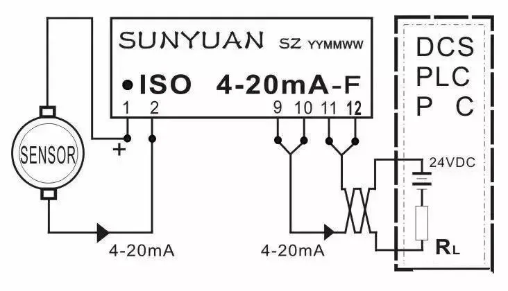
Wiring Examples (assuming standard PLC terminal numbering):
- Two-wire current: PLC supplies 24V on positive terminal; sensor modulates return current.
- Four-wire: Sensor powered externally; signal fed to PLC input.
- Voltage signals: Direct connection with proper jumper settings on the PLC module.
Engineers must consider cable length, shielding, grounding, and EMC practices to minimize interference.
PCB and Control System Integration Considerations
- Signal Conditioning Boards: Custom PCBs with isolation amplifiers, filters, and surge protection improve signal quality.
- I/O Module Design: Multilayer PCBs with proper grounding planes and impedance control for analog sections.
- Flexible Circuits: Useful for connecting sensors in tight or moving installations.
- Power Distribution: Segregated power and signal routing on PCBs to reduce crosstalk.
- Testing and Reliability: In-circuit testing, environmental stress screening, and compliance with industrial standards (e.g., IEC for EMC).
Advanced manufacturing supports high-density layouts, thermal management for always-on modules, and scalable production for OEM automation equipment.
Industry Trends
Modern systems increasingly use smart sensors with digital communication, reducing analog wiring complexity. IO-Link and Ethernet-based protocols simplify integration while providing diagnostics. Hybrid analog/digital approaches remain common in legacy upgrades.
By applying sound connection practices and leveraging sophisticated PCB platforms, industrial automation designers can achieve precise, noise-immune, and maintainable sensor networks that enhance overall system performance and uptime.
FAQ
Q1: When should I choose a two-wire versus four-wire sensor?
A1: Two-wire for simpler, lower-cost installations with shorter runs; four-wire for higher performance, longer distances, or applications requiring better isolation and power.
Q2: Why is 4-20mA preferred over voltage signals in industrial settings?
A2: Current loops offer superior noise immunity over long cables and enable loop powering, while voltage signals are more susceptible to drop and interference.
Q3: How do PCBs support reliable PLC-sensor connections?
A3: Through signal conditioning, isolation, proper grounding, and controlled impedance layouts that maintain signal integrity from sensor to PLC I/O.