Displacement Sensor Components
The structure of a displacement sensor varies with its operating principle. Common components include:
1. Photoelectric (optical) sensor
- Light source: usually an LED or a laser to emit the light beam.
- Receiver: typically a photoresistor, photodiode, or phototransistor to receive reflected light.
- Amplifiers and signal processing circuits: amplify and process the received optical signal.
- Control circuits: control the operation of the light source and receiver.
2. Volumetric sensor
- Measuring chamber: contains the measured medium.
- Pressure or level sensor: measures changes in volume.
- Pressure transmitter: converts the measured value into an electrical signal.
- Control circuits: control and process the sensor signals.
3. Cantilever (beam) sensor
- Cantilever structure: made of elastic material whose shape changes with displacement.
- Strain gauges: mounted on the cantilever to measure deformation.
- Strain gauge amplifier: amplifies and processes the strain gauge signals.
- Control circuits: control and process the sensor signals.
4. Piezoresistive sensor
- Piezoresistive material: typically conductive rubber or silicon carbide, whose resistance changes with displacement.
- Circuit board: connects the electrodes of the piezoresistive material.
- Signal conditioning circuits: measure and process the resistance changes.
5. Magnetic sensor
- Magnetic-sensitive element: typically MR (magnetoresistive) or Hall element to sense magnetic field changes.
- Magnetic field generator: usually a permanent magnet or electromagnetic coil to generate the field.
- Signal amplifiers and processing circuits: amplify and process the signals from the magnetic element.
6. Ultrasonic sensor
- Ultrasonic transmitter: generates ultrasonic pulses.
- Ultrasonic receiver: receives reflected ultrasonic signals.
- Control circuits: control the transmitter and receiver and process signals.
Wiring Methods for Displacement Sensors
Wiring varies by sensor model and operating method. The main configurations are two-wire, three-wire, and four-wire systems.
Two-wire: Connect the sensor power to the positive terminal of the switching power supply and connect the sensor signal line to the equipment input. If the equipment provides a negative input terminal, tie that input negative to the switching power supply negative.
Three-wire: Match the sensor wires to the device ports. If the device has three terminals, connect the sensor's power positive, power negative, and signal output to the device's three terminals directly. If the device provides four terminals, follow the device's terminal assignments and connect the sensor's negative and the power supply negative per the device wiring requirements.
Four-wire: Connect the power and signal lines separately to the corresponding device terminals.
Principles and Applications of Displacement Sensors
Displacement sensors measure an object's relative position or movement. Their operating principles depend on the sensing technology. Common types and applications include:
- Photoelectric sensors: use optical effects to detect position changes. Applications include paper detection in printers and position detection in industrial automation.
- Volumetric sensors: determine displacement by measuring changes in occupied volume. Applications include fuel metering and liquid level measurement.
- Cantilever sensors: measure displacement via impedance or strain changes in elastic materials. Applications include pressure sensors and force sensors.
- Piezoresistive sensors: measure displacement through resistance changes of piezoresistive materials. Applications include touchscreens and force-feedback devices.
- Magnetic sensors: detect displacement using magnetic field sensing. Applications include read/write head positioning in disk drives and vehicle speed sensing.
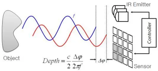
- Ultrasonic sensors: use the time of flight of ultrasonic pulses to calculate distance and displacement. Applications include ranging equipment and smart door locks.