Basic Concepts of Radar Antenna Patterns
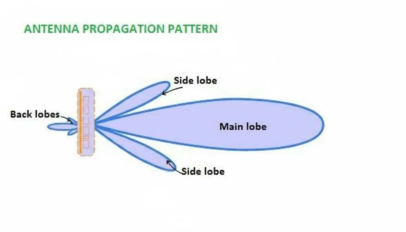
Radar antennas cannot focus all transmitted energy into a single narrow beam. The radiation pattern consists of a main lobe (the primary high-gain direction) and multiple sidelobes (unwanted secondary radiation directions).
- The main lobe is centered on the direction of maximum radiation, typically defined within the -3 dB contour (half-power beamwidth).
- Sidelobes are smaller lobes surrounding the main beam.
- Backlobes point approximately opposite the main lobe.
Key parameters include:
- Half-Power Beamwidth (-3 dB beamwidth): Angular width where power drops to 50% of peak.
- First-Null Beamwidth: Angle between the first nulls on either side of the main lobe.
Narrower beamwidth improves resolution and range, but sidelobes are inevitable due to finite antenna aperture and diffraction effects.
Problems Caused by Sidelobes
Even though sidelobe levels are significantly lower than the main lobe (typically -13 dB to -30 dB), they create several operational challenges:
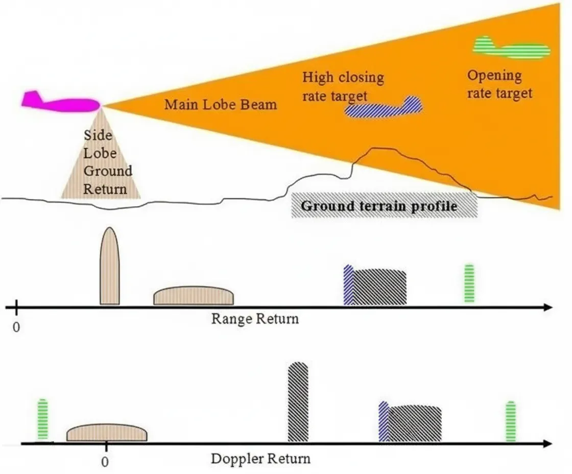
Sidelobe Clutter: When the main beam scans near the horizon, sidelobes can illuminate the ground or sea surface. Because these surfaces are much closer than airborne targets, even weak sidelobe returns can produce clutter echoes comparable in strength to desired targets. Increasing transmit power does not resolve this; advanced Doppler processing helps but cannot fully eliminate the issue.
Increased Detectability and Vulnerability: Strong sidelobes make the radar easier for adversaries to detect via electronic support measures (ESM) or radar warning receivers (RWR). Enemies can intercept sidelobe signals earlier, analyze waveforms, geolocate the radar, or inject deceptive jamming/spoofing signals into sidelobes while the main beam points elsewhere.
Jamming Susceptibility: Lower sidelobe isolation reduces the jamming-to-signal ratio advantage for off-axis jammers, but high sidelobes still allow effective electronic attack.
Ultra-Low Sidelobes: Generally considered better than -40 dB relative to peak gain. These dramatically reduce detection range by adversaries (due to two-way path loss) and limit jamming effectiveness, enhancing low-probability-of-intercept (LPI) characteristics.
Design Strategies for Low Sidelobes
Achieving and maintaining low sidelobes requires:
- Optimized antenna array tapering (amplitude/phase distribution).
- Precision manufacturing and calibration.
- Advanced materials and structures (e.g., phased arrays with careful element spacing).
- Measurement and verification in anechoic chambers.
Relevance to PCB and High-Frequency Electronics Design
Modern radar systems, especially automotive radar, phased-array radars, and compact sensors, rely on integrated RF front-ends and antenna arrays:
- PCB Antenna Design: Microstrip patches, substrate-integrated waveguides (SIW), or LTCC-based arrays must achieve precise amplitude/phase control for sidelobe suppression.
- Signal Integrity & RF Layout: Controlled impedance traces, minimal via stubs, shielding, and low-loss laminates are critical at mmWave frequencies to prevent pattern distortion.
- Integration Challenges: Multi-layer HDI PCBs combine RF, analog, and digital sections while maintaining isolation to avoid self-generated interference that could elevate effective sidelobes.
- Manufacturing Precision: Tight tolerances on trace geometry, dielectric constants, and assembly accuracy directly impact beam patterns and sidelobe levels.
High-frequency PCB expertise is essential for cost-effective, high-performance radar modules in ADAS, drones, industrial sensing, and defense applications.
FAQ
Q1: What are the main problems caused by radar sidelobes?
A1: Clutter from ground/sea returns, increased detectability by adversaries, and higher susceptibility to jamming or spoofing.
Q2: How are ultra-low sidelobes defined?
A2: Typically >40 dB below main lobe peak gain, significantly improving LPI performance and reducing electronic warfare vulnerabilities.
Q3: Why is PCB technology important for radar sidelobe performance?
A3: It enables precise RF antenna arrays, low-loss interconnects, and high-isolation layouts necessary for maintaining designed radiation patterns in compact systems.