Overview
This application note assumes the user is programming an Allegro fully integrated reverse-bias Hall-effect switch, or has designed an appropriate magnetic circuit to accommodate the programming range of a programmable unipolar Hall-effect switch. Programming is achieved by controlling the Schmitt trigger offset, as shown in the functional block diagram in Figure 1. The corresponding datasheet provides the method for programming the device.
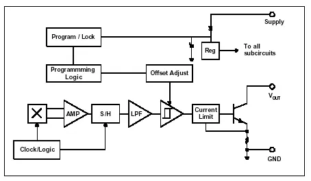
Figure 1. Programmable switch functional block diagram
Reference Target Flux vs. Position
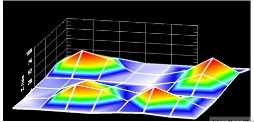
A plot of the reference target's magnetic flux density versus position (degrees of rotation) helps illustrate programming and its effect on Hall device performance; see Figure 2. Each curve represents a different installation air gap. A single tooth is used to represent a typical ferrous target for proximity sensing. A translating metal target rather than a rotating one would produce a similar plot, with the horizontal axis in millimeters instead of degrees. Since proximity sensing can use either rotating or translating targets, this document uses rotation by convention. A detailed description of the reference target is in Appendix A.
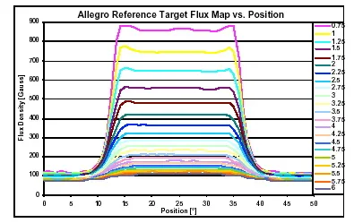
Figure 2. Flux map of the reference target
Note that any Schmitt threshold is represented by two horizontal lines on the plot, separated by a typical magnetic hysteresis of 20 gauss. The forward switching point is called BOP (magnetic operate point), and the reverse switching point is called BRP (magnetic release point). When the signal moves from the valley to the tooth, the output switches at BOP; when the signal moves from the tooth to the valley, the output switches at BRP (see Figure 3).
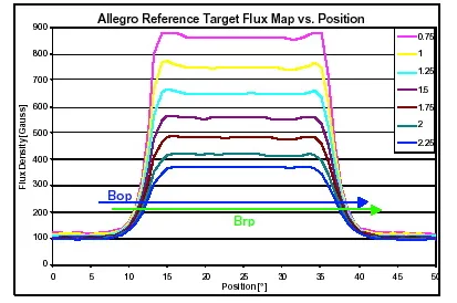
Figure 3. Enlarged view of the valley-to-tooth region
Figure 4 is a further enlargement of the BOP switching point as it moves from valley to tooth. Two vertical lines are drawn to show the switching point positions for a given BOP when the installation air gap is 0.75 mm and 2.25 mm. Note that, over this air gap range from 0.75 mm to 2.25 mm, the difference between gaps corresponds to approximately 1.5 degrees. This is the expected relative accuracy of switch position for a given threshold and installation air gap.
Proximity Sensing
In proximity sensing applications, the switch point is programmed to achieve the desired position, which can be in millimeters or degrees on the horizontal axes of Figures 2, 3 and 4. Programming allows compensation for mechanical offsets introduced during assembly, which can tightly control the switch position. For example, if the desired switch point in Figure 4 is 12 degrees and the device is installed with a 0.75 mm air gap, the BOP input should be set to approximately 400 gauss, higher than the level shown in the figure. If the device is installed with a 2.25 mm air gap, the BOP should be set to just above 200 gauss or slightly lower than the value indicated in Figure 4.