Temperature sensors are fundamental components in virtually every electronic system, from automotive powertrains and industrial process control to medical devices and consumer electronics. In PCB manufacturing and design, accurate temperature measurement depends on proper sensor selection, precise layout, thermal management, signal integrity, and reliable interconnection. Engineers must address material compatibility, noise immunity, and long-term stability at the board level to ensure consistent performance across operating environments.
Common Temperature Sensor Types and PCB Integration Requirements
Four widely used temperature sensor technologies dominate PCB applications: NTC thermistors, RTDs (resistance temperature detectors), thermocouples, and semiconductor-based sensors (such as silicon bandgap or integrated circuit sensors). Each type presents unique electrical, mechanical, and thermal characteristics that directly influence PCB layout, stack-up, and fabrication choices.
NTC thermistors offer high sensitivity and fast response in a compact package, making them suitable for consumer and automotive applications. On PCBs, they require stable bias currents, low-noise analog traces, and placement away from heat-generating components to avoid self-heating errors. RTDs provide superior accuracy and long-term stability, commonly used in industrial instrumentation. Their low resistance change demands four-wire or three-wire Kelvin connections on the PCB to eliminate lead resistance effects. Thermocouples excel in extreme temperature ranges and harsh environments but generate very small millivolt-level signals, necessitating careful shielding, cold-junction compensation circuitry, and high-quality thermocouple extension wires or PCB terminals. Semiconductor sensors integrate signal conditioning on-chip, simplifying PCB design but requiring proper power supply decoupling and thermal coupling to the measured medium.
NTC Thermistor Operation, Advantages, and PCB Implementation
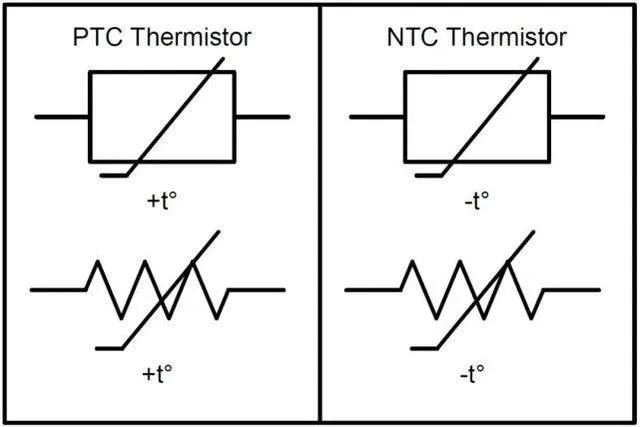
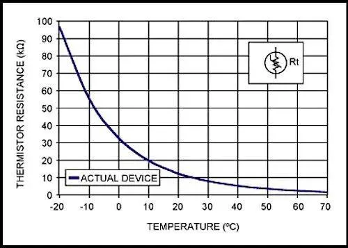
NTC thermistors exhibit a strong negative temperature coefficient, with resistance decreasing as temperature rises. Their high sensitivity allows precise measurements over narrow ranges, while small size and low cost support high-volume PCB assembly. Installation on PCBs typically involves surface-mount or through-hole packages with solder joints that must withstand thermal cycling without cracking. Designers place NTCs close to the heat source or target area while ensuring adequate thermal resistance from nearby power components. Decoupling capacitors and guard traces reduce noise pickup on the high-impedance measurement path. Material selection favors high-Tg laminates when operating temperatures exceed 125 °C to prevent delamination around the sensor pads.
RTD Sensor Operation, Installation, and PCB Precautions
RTDs, typically platinum-based (Pt100 or Pt1000), deliver excellent linearity and repeatability. Their resistance increases predictably with temperature, enabling high-accuracy measurements when properly conditioned. On PCBs, RTDs require precise current sources (often 1 mA or less) and differential measurement to minimize self-heating and lead resistance. Four-wire configurations are preferred for best accuracy, demanding dedicated trace routing and connector pins. Thermal coupling between the RTD element and the measured surface is critical; designers often use thermal vias or copper pours to improve heat transfer while maintaining electrical isolation. Precautions include avoiding high-current traces near RTD wiring, using low-thermal-EMF materials, and applying conformal coating for protection in humid or corrosive environments.
Thermocouples and Differences from RTDs on PCBs
Thermocouples generate voltage based on the Seebeck effect between two dissimilar metals, offering wide temperature range, fast response, and robustness. Unlike RTDs, they require cold-junction compensation, usually implemented with an onboard temperature sensor or dedicated IC on the PCB. Signal levels are low (tens of microvolts per degree), so PCB layout must minimize thermoelectric voltages through symmetric routing, isothermal terminal blocks, and shielding. Compared with RTDs, thermocouples tolerate higher temperatures and vibration but offer lower accuracy and require more complex signal conditioning. PCB designers often dedicate separate analog front-end sections with high-CMRR amplifiers and filtering to handle thermocouple signals without introducing offset or noise.
Accuracy Challenges and PCB-Level Mitigation Strategies
Inaccurate readings frequently stem from self-heating, poor thermal contact, lead resistance, electromagnetic interference, and reference junction errors. On the PCB, these issues are mitigated through:
- Optimized copper weight and thermal via arrays to enhance heat transfer without excessive self-heating.
- Star grounding and separation of analog sensor traces from digital and power planes.
- Controlled-impedance routing for high-frequency or long-distance sensor connections.
- Proper component placement that maintains consistent temperature gradients across the board.
- Use of high-stability reference voltages and low-drift amplifiers in the signal chain.
Failure analysis at the PCB level often reveals issues such as cracked solder joints, moisture ingress, or thermal expansion mismatch between sensor packages and the substrate.
PCB Design and Manufacturing Best Practices for Temperature Sensors
Effective integration requires attention to stack-up design (high-Tg FR4 or polyimide for elevated temperatures), copper thickness for current-carrying and thermal spreading, and via structures that support both electrical and thermal performance. Surface finishes such as ENIG or immersion silver ensure reliable sensor pad connections. For high-reliability applications, automotive-grade or medical-grade laminates and controlled CTE materials reduce stress on sensor packages. Manufacturing processes must accommodate tight tolerances on sensor footprints and support in-circuit or functional testing of temperature channels. Reliability testing includes thermal cycling, humidity exposure, and vibration to validate long-term stability.
Conclusion
Accurate and reliable temperature sensing on PCBs demands a holistic approach that combines appropriate sensor technology with optimized layout, thermal management, and robust fabrication. By addressing signal integrity, mechanical stress, and environmental factors from the earliest design stages, engineers achieve superior measurement precision and extended product life. Whether in automotive electronics, industrial control systems, or medical instrumentation, specialized PCB manufacturing capabilities remain essential for realizing the full performance of thermistors, RTDs, and thermocouples. Aivon's expertise in high-reliability and high-frequency PCB fabrication supports the demanding requirements of modern temperature-sensing applications across multiple industries.