Overview
5G is the fifth-generation mobile communication standard defined by the International Telecommunication Union (ITU). The official name is IMT-2020. 5G aims to enable ubiquitous connectivity rather than only increasing peak data rates as previous generations did.
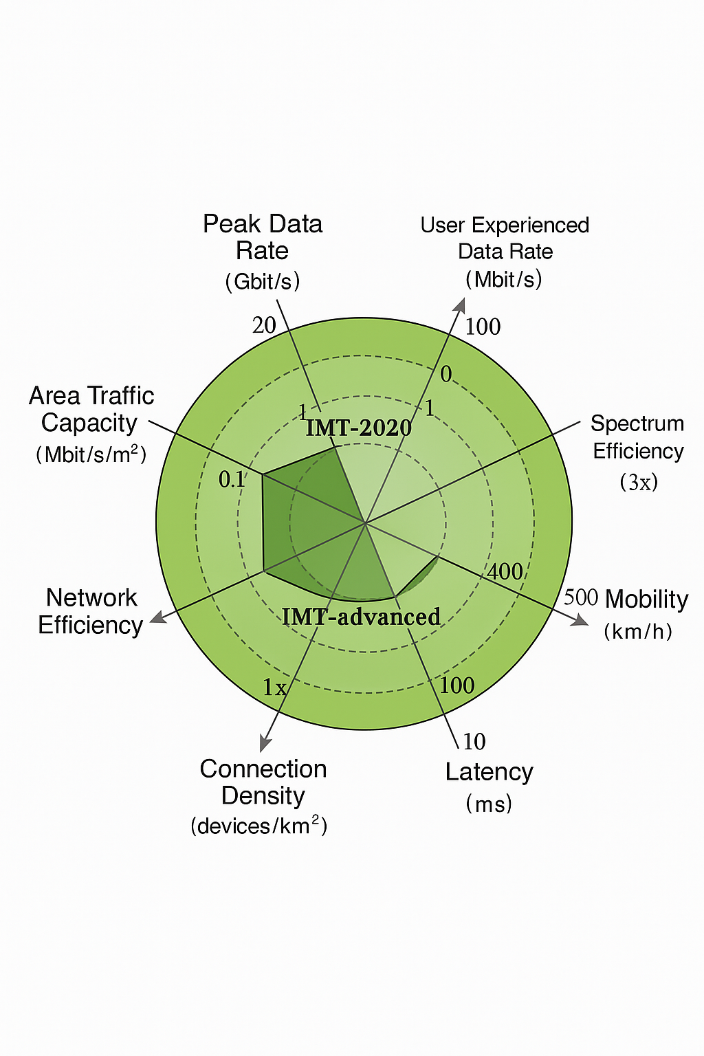
Key 5G Performance Targets
5G considers multiple technical indicators such as peak data rate, user-experienced data rate, spectral efficiency, mobility, latency, connection density, network energy efficiency, and traffic density. The specification targets include up to 20 Gbit/s peak data rate, around 100 Mbit/s user-experienced throughput, 1 ms end-to-end latency, 10 Gbps cell throughput, up to 1 million connections per square kilometer, and support for mobility up to 500 km/h.
Three Main 5G NR Use Cases
5G NR defines three primary service categories to address a wide range of applications:
- Enhanced Mobile Broadband (eMBB)
- Massive Machine-Type Communications (mMTC)
- Ultra-Reliable Low-Latency Communications (uRLLC)
Enhanced Mobile Broadband (eMBB): targets high data-rate services such as AR, VR, and 4K/8K video that require large capacity to deliver good user experience.
Massive Machine-Type Communications (mMTC): supports massive numbers of low-cost, low-power devices for IoT scenarios such as smart cities and smart buildings.
Ultra-Reliable Low-Latency Communications (uRLLC): targets industry and mission-critical applications with strict latency and reliability requirements, including autonomous driving, industrial control, and remote medical services.
5G NR Spectrum Distribution
Wireless services require radio spectrum. To support diverse 5G use cases, additional spectrum is allocated and organized into two ranges: FR1 and FR2 (Frequency Range).
FR1: the primary 5G frequency range below 6 GHz, often called sub-6 GHz. It spans approximately 450 MHz to 6000 MHz. Lower frequencies provide better penetration and coverage and are widely used for broad area deployments.
Many current national 5G deployments use these sub-6 GHz bands. Operator allocations vary by market; in some regions broadcasters also hold 700 MHz spectrum, which is valuable for wide-area coverage.
Commonly used 5G bands include n78 (around 3.5 GHz), which has a mature ecosystem and is widely adopted, while other bands such as n41 and n79 may have less mature supply chains and require additional industry effort to deploy.
FR2: the millimeter-wave range with much higher frequencies (for example around 28 GHz). FR2 spans roughly 24.25 GHz to 52.6 GHz. Millimeter-wave bands are spectrally rich and support very large bandwidths with relatively low interference, but have more limited propagation.
NSA and SA: Two Deployment Models
5G deployment is evolutionary and can leverage existing 4G infrastructure to accelerate rollout and reduce cost. Two main deployment architectures are Non-Standalone (NSA) and Standalone (SA).
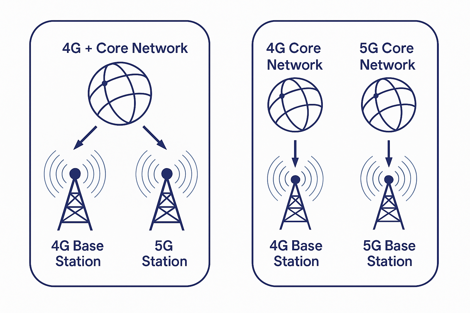
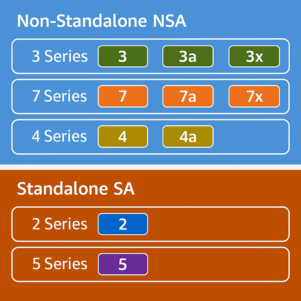
NSA (Non-Standalone): reuses the existing 4G core and integrates 5G radio. NSA configurations combine 4G core/5G core with 4G and 5G base stations in various options (often referred to by category numbers such as 3, 4, 7).
SA (Standalone): deploys a full 5G system with a new 5G core and base stations, introduces new network functions and interfaces, and makes extensive use of virtualization and software-defined networking. Common SA options include category 2 and 5 configurations.
NSA enables faster and lower-cost initial rollouts, helping operators quickly enter the market. However, NSA adds complexity because 4G and 5G must interwork at the access network level, which can increase handover latency and limit certain 5G capabilities. Ultimately, most deployments are expected to evolve toward SA.
5G Frame Structure
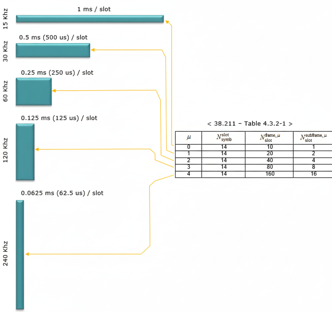
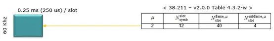
5G NR shares basic timing with LTE: radio frames remain 10 ms long and are divided into 10 subframes of 1 ms each, with two half-frames per frame. To support diverse applications, 5G NR defines flexible substructure: numerology (subcarrier spacing) and slot lengths can be varied.
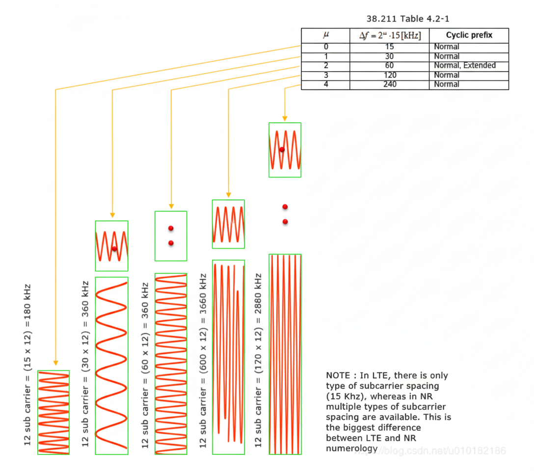
Unlike LTE's fixed 15 kHz subcarrier spacing, 5G NR supports multiple numerologies: 15 kHz, 30 kHz, 60 kHz, 120 kHz, and 240 kHz. One resource block (RB) consists of 12 subcarriers. Different subcarrier spacing options correspond to different slot durations: as subcarrier spacing increases, slot length decreases.
In LTE, uplink/downlink configuration is done at the subframe level. In 5G NR, uplink and downlink can be configured at symbol granularity, offering greater flexibility.
With normal cyclic prefix (CP), each slot contains 14 OFDM symbols. Each symbol can be downlink (D), uplink (U), or flexible (X). For 15 kHz spacing, one OFDM symbol duration is 66.67 μs; 14 symbols take approximately 0.93338 ms, leaving the remainder of the 1 ms slot for CP.
With extended CP, each slot contains 12 symbols.
Notes on numerology and CP:
- Phase noise and Doppler shift set practical lower limits for subcarrier spacing; too small spacing increases sensitivity to frequency offset and degrades inter-subcarrier orthogonality.
- Among the supported spacings, 60 kHz is not used for synchronization and 240 kHz is not used for data transport. 60 kHz supports both normal and extended CP configurations.
- For frequency ranges below 6 GHz, configurations typically use 15 kHz, 30 kHz, and 60 kHz. For frequency ranges above 6 GHz, configurations typically use 120 kHz and 240 kHz.
- The cyclic prefix length constrains the maximum usable subcarrier spacing because CP must exceed the maximum multipath delay spread; very short CP cannot cope with large multipath delays.
5G NR defines many slot formats and additional details that are covered in subsequent standards and specifications.
5G Modulation Methods
Modulation maps information onto a carrier waveform suitable for radio transmission. A sine wave carrier has amplitude, phase, and frequency; digital modulation manipulates one or more of these parameters to carry bits.
Basic digital modulation types include:
- ASK: amplitude varies with the modulating signal
- FSK: frequency varies with the modulating signal
- PSK: phase shifts encode information
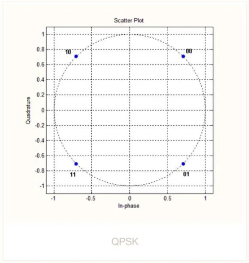
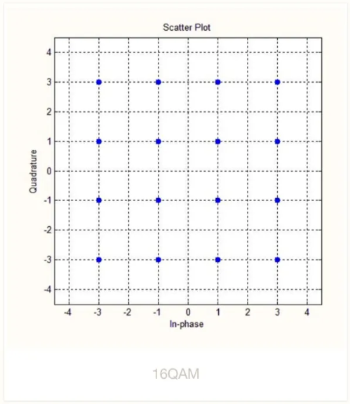
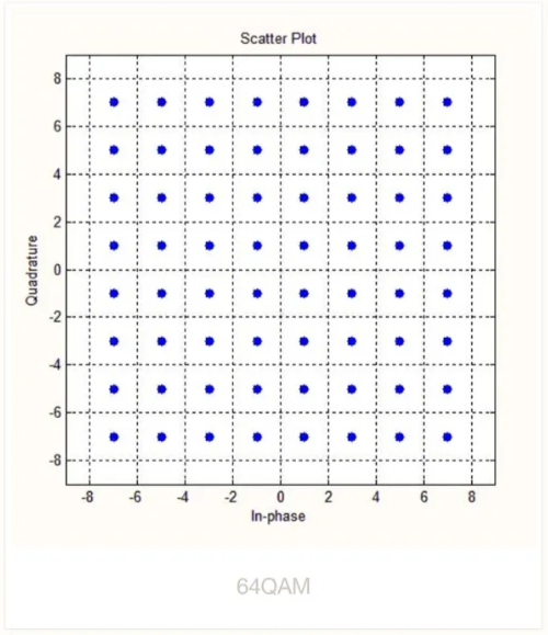
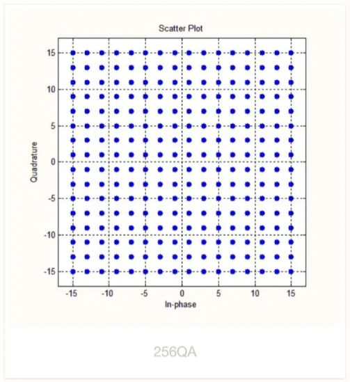
Many modern schemes are combinations or refinements of these. QAM (quadrature amplitude modulation) jointly modulates amplitude and phase and maps bits to constellation points (e.g., 4QAM, 16QAM, 64QAM, 256QAM). OFDM splits a wideband channel into many orthogonal subcarriers and transmits parallel lower-rate streams.
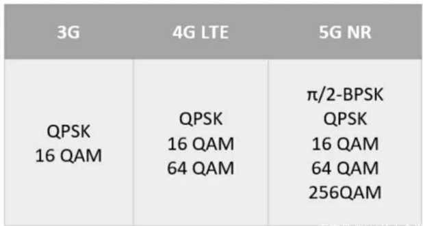
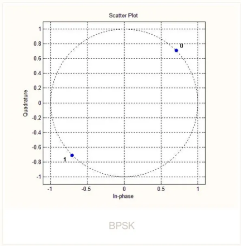
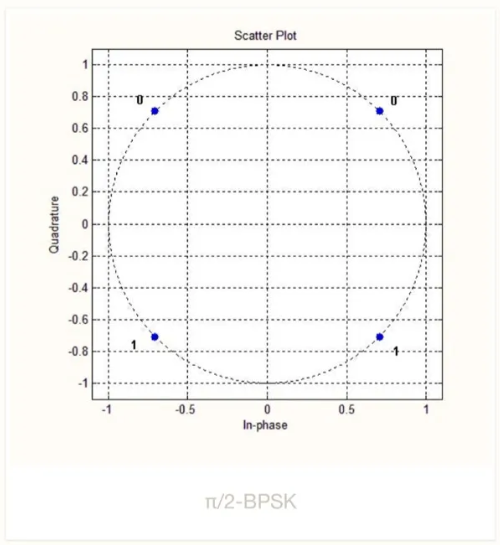
5G supports a variety of modulations including PSK variants such as π/2-BPSK and QPSK and QAM orders including 16QAM, 64QAM, and 256QAM. Constellation diagrams visualize the amplitude and phase states of modulation symbols using an in-phase (I) axis and a quadrature (Q) axis.
Example constellation diagrams:
Beamforming
Beamforming is an antenna-array signal processing technique for directional transmission and reception. By adjusting the phases and amplitudes of array elements, signals from certain directions add constructively while signals from other directions cancel, producing directional beams. This concentrates electromagnetic energy toward desired receivers and improves coverage and received signal strength.
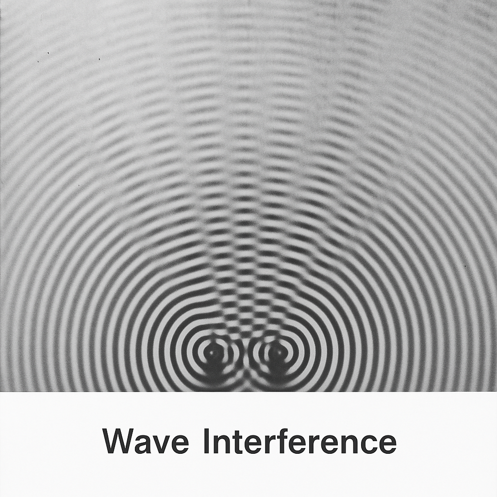
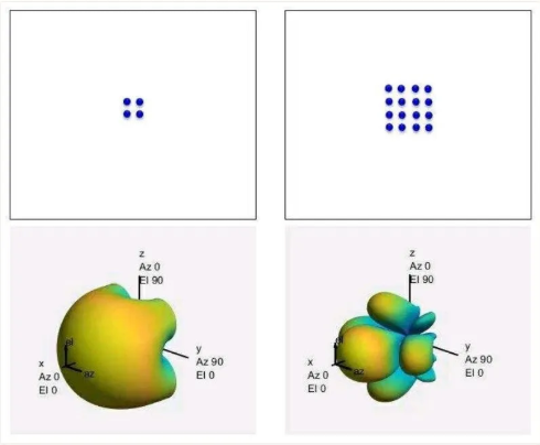
With omnidirectional transmission, much energy is wasted; beamforming focuses energy into beams aimed at user devices. This is particularly important for higher 5G frequencies and millimeter-wave bands where propagation range is limited. Increasing the number of antenna elements produces narrower beams and greater directivity; 5G commonly uses large antenna arrays.
Massive MIMO is a key 5G technology for increasing system capacity and spectral efficiency. With many antenna elements, phenomena such as additive noise and small-scale fading average out, allowing significant throughput gains. Higher carrier frequencies reduce antenna element size, enabling many elements to be packed into the same physical aperture and enabling array and beamforming techniques to compensate for path loss.
Beamforming can be implemented digitally or in analog:
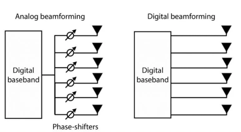
Digital beamforming operates on baseband digital signals (before DAC on the downlink and after ADC on the uplink) and can precisely control amplitude and phase for each radio chain. It supports multi-user, multi-stream transmission and flexible beam control. However, each RF chain requires its own DAC/ADC, mixer, filters, and power amplifiers, increasing cost and power consumption.
Analog beamforming adjusts phases and amplitudes in the RF domain after DAC or before ADC. It reduces hardware complexity because multiple antenna elements can be driven by a single RF chain with analog phase shifters, but it offers less flexibility than full digital beamforming.
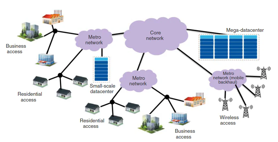
New 5G Front-Haul Interfaces: CPRI and eCPRI
Early base station architectures colocated the radio unit (RRU) and baseband unit (BBU) indoors, requiring long feeder cables to rooftop antennas. Long feeders introduce significant loss, so higher transmit power was needed, increasing complexity and power consumption.
Distributed architectures separated BBU and RRU, moving power-hungry RRUs closer to antennas on towers and reducing feeder loss. To standardize the digital interface between BBU and RRU, the Common Public Radio Interface (CPRI) was defined. CPRI transports physical-layer data and associated physical-layer information between remote radio equipment and the central unit, enabling multi-vendor interoperability.
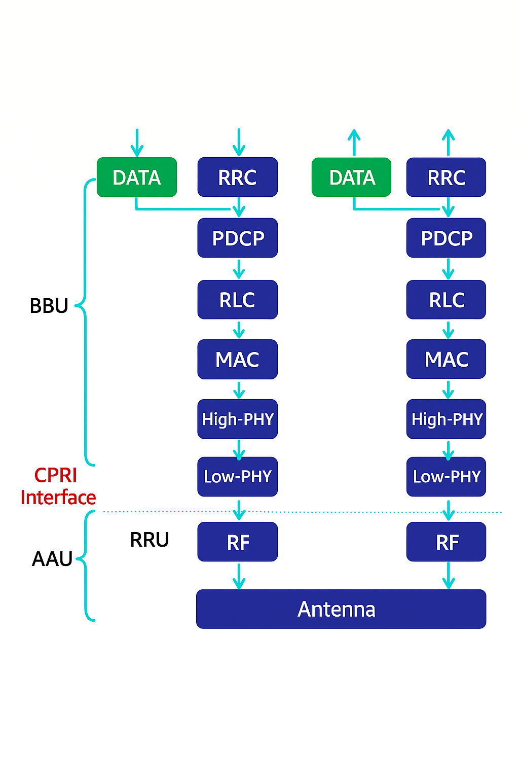
CPRI options define multiple rates up to 12 Gbps. However, 5G trends such as massive MIMO and wider carrier bandwidths dramatically increase front-haul bandwidth requirements. For example, a 100 MHz carrier with 64 antenna ports can require on the order of 172.8 Gbps using traditional CPRI for sub-6 GHz deployments.
eCPRI reduces front-haul bandwidth by moving some PHY processing from the centralized unit to the remote radio unit. By shifting high-PHY functions toward the RRU and keeping only necessary higher-layer data on the front haul, eCPRI can greatly reduce required optical rates. Using the earlier example, the same 100 MHz carrier with 64 antennas would require about 24.3 Gbps with eCPRI instead of 172.8 Gbps with traditional CPRI, i.e., roughly 14% of the original bandwidth.
eCPRI and flexible functional splits are expected to be mainstream in future 5G networks to support advanced radio techniques while keeping front-haul requirements manageable.
How 5G Establishes a Connection (Random Access)
To connect, a UE must synchronize with the network. After detecting synchronization signals (SSB), the UE has downlink sync and must perform random access to achieve uplink synchronization and request radio resources. Random access (RACH) in 5G, similar to LTE, supports two access modes:
- Contention-Based Random Access (CBRA)
- Contention-Free Random Access (CFRA)
In contention-based access, UEs transmit a PRACH preamble chosen randomly from a set. If multiple UEs choose the same preamble and transmit simultaneously, a collision occurs and the gNodeB uses contention resolution mechanisms.
Contention-based random access typically follows four messages:
- Random Access Preamble (MSG1)
- Random Access Response (MSG2)
- Scheduled Transmission (MSG3)
- Contention Resolution (MSG4)
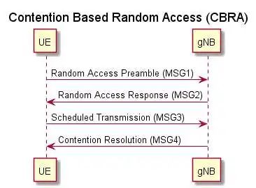
MSG1: UE sends the chosen preamble. MSG2: gNodeB responds and allocates temporary identifiers and uplink/downlink scheduling. MSG3: UE transmits scheduled uplink data. MSG4: gNodeB resolves contention using identifiers carried on control or data channels.
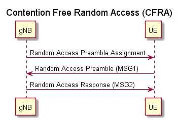
In some cases contention is unacceptable. For CFRA the gNodeB assigns a dedicated preamble to the UE, avoiding collisions. Dedicated preambles can be provided via RRC signaling or physical-layer control (DCI on PDCCH). If dedicated resources are exhausted the gNodeB can request contention-based access.
CFRA typically includes:
- Random Access Preamble Assignment
- Random Access Preamble (MSG1)
- Random Access Response (MSG2)
Random access is used in many scenarios, including initial RRC connection and RRC connection re-establishment (prefer contention-based), handover (prefer contention-free), downlink or uplink data arrival, and beam failure recovery, among others. Where possible, contention-free access is preferred for time-critical procedures.
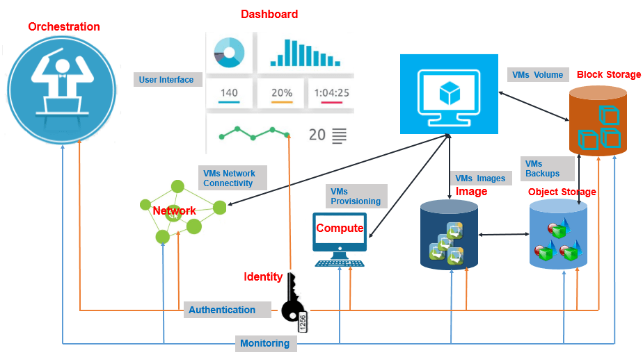
5G Network Slicing
Network slicing is an on-demand network partitioning method that creates multiple logical end-to-end virtual networks over a shared physical infrastructure. Each slice is logically isolated and can span the radio access network, transport network, and core network to meet different service requirements. A typical slice can include a radio sub-slice, a transport/bearer sub-slice, and a core network sub-slice.
Different 5G services such as vehicular networks, industrial automation, remote medical services, and VR/AR have diverse requirements for user capacity, QoS, bandwidth, latency, and mobility. Slicing enables operators to provision customized virtual networks with tailored functionality and isolation so that a failure or overload in one slice does not affect others.
Slices should provide end-to-end integrity, on-demand customization, and secure isolation.