What Does Reverse Engineering an ECU Printed Circuit Board Involve?
Reverse engineering an Engine Control Unit (ECU) printed circuit board (PCB) means systematically dissecting and scrutinizing its design, functionality, and internal connections. This is done without relying on original blueprints or official documentation. The primary goal is often to reconstruct the circuit diagram, pinpoint individual components, or even modify the board for specific applications, such as performance tuning or repairing a vehicle's electronic system.
This intricate process demands a blend of technical expertise, specialized instrumentation, and a meticulous strategy to unravel the complexities inherent in the board's construction. Through a careful, step-by-step methodology, one can uncover the hidden logic behind the ECU's operation.
Why Do Engineers and Hobbyists Reverse Engineer ECU PCBs?
Exploring the internal workings of an ECU PCB offers significant advantages for both automotive professionals and enthusiasts. The motivations for undertaking such a detailed analysis are varied, ranging from practical repairs to advanced research.
Key Reasons for ECU Reverse Engineering
● Repairing Obsolete Systems: Many older vehicles rely on ECUs that are no longer produced, and their original technical specifications may be lost. Reverse engineering provides a pathway to repair or replace malfunctioning parts, extending the life of vintage automobiles.
● Enhancing Performance: To fine-tune an engine for better performance, fuel economy, or reduced emissions, it's often necessary to comprehend the PCB's architecture. This understanding enables precise alterations to circuits or firmware.
● Research and Development: Engineers frequently analyze existing designs, whether from competitors or legacy systems, to extract valuable insights. This knowledge then informs the creation of more advanced and efficient solutions.
● Cost-Effective Alternatives: In scenarios where sourcing rare or expensive replacement ECUs is challenging, recreating or mending an existing unit through reverse engineering can be a far more economical choice.
What Essential Tools Are Needed for ECU PCB Analysis?
Undertaking the reverse engineering of an ECU PCB requires a specific set of tools for effective inspection, documentation, and analysis. Equipping yourself with the right instruments is crucial for success.
Fundamental Equipment
● Multimeter: Indispensable for checking voltage levels, confirming continuity of traces, and measuring resistance values across components. For example, it can verify a resistor's ohmic value or a capacitor's integrity.
● Magnification Devices: A magnifying glass or a dedicated microscope is vital for examining minuscule components and fine traces, especially in densely populated areas of the PCB.
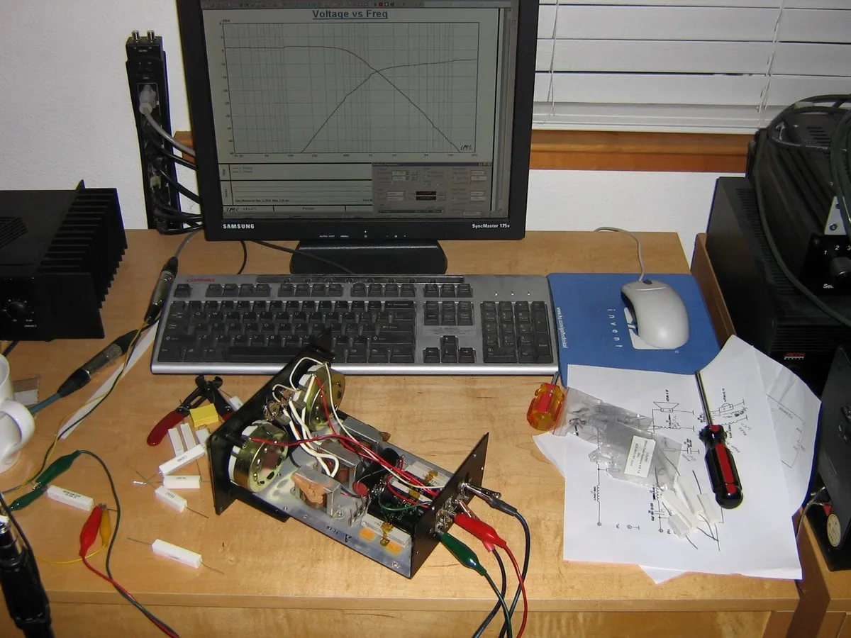
● High-Resolution Camera: A digital camera or even a modern smartphone is necessary for capturing detailed images of this HDI PCB, which serve as critical documentation and reference points throughout the process.
● Soldering & Desoldering Station: These tools are required for carefully removing components if a closer examination or isolated testing is necessary.
● Schematic Capture Software: As connections are discovered, specialized software helps in digitally recreating the circuit diagram, organizing the findings into a clear, understandable format.
● Oscilloscope: Highly useful for observing and analyzing signal behavior, such as clock frequencies or data communication lines, providing insights into the board's dynamic operations (e.g., verifying a 5V signal at 1MHz).
Advanced Tooling (Optional)
● X-Ray Imaging: For complex multilayer PCBs, X-ray equipment can non-destructively reveal internal traces and vias that are otherwise invisible from the surface, offering a complete view of the board's internal routing.
● Workstation Setup: A dedicated, organized workstation is paramount for efficient workflow and to keep all tools and components accessible.
How to Safely Prepare an ECU PCB for Disassembly and Analysis
Prioritizing safety is crucial when working with sensitive electronic components like an ECU PCB. Proper preparation not only protects the equipment but also safeguards the individual performing the analysis.
Before beginning any hands-on work, always ensure the ECU is completely disconnected from any power source or vehicle battery. This precaution is vital to prevent accidental short circuits or potential damage to the delicate electronics.
Work in an environment free from electrostatic discharge (ESD). Utilize an anti-static wrist strap and an ESD-safe mat to dissipate any static electricity, which could otherwise permanently damage sensitive integrated circuits and other components. Handle the PCB with extreme care, avoiding any undue force that might break fragile traces or dislodge components. Once these safety measures are in place, the ECU can be carefully removed from its protective casing, typically by unscrewing fasteners that secure the enclosure, to expose the PCB for detailed inspection.
Documenting the ECU PCB: A Foundation for Success
Thorough documentation forms the bedrock of a successful reverse engineering project. Before altering anything on the board, systematically capture detailed visual records from all angles.
Begin by taking high-resolution photographs of both sides of the PCB. These images should clearly show:
● Component Markings: Capture all labels, part numbers, and any other identifying marks on integrated circuits (ICs), resistors, capacitors, and other discrete components.
● Trace Routes: Photograph the patterns of conductive traces and all solder joints, noting any unique routing strategies.
● Physical Anomalies: Document any visible signs of damage, previous repairs, or modifications that might indicate the board's history or potential issues.
Beyond photography, it's beneficial to create a labeled reference diagram or annotate your images. Pay close attention to any visible vias, which are small holes connecting different layers of a multi-layer PCB, as they reveal critical inter-layer connections.
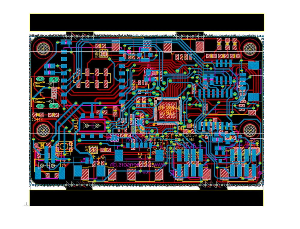
Interpreting the ECU PCB Layout and Structure
Grasping the physical arrangement of components and traces, known as the PCB layout, is a fundamental step in reverse engineering. This understanding provides a structural map of the board.
Mapping Functional Blocks
Most ECU PCBs are logically segmented into distinct functional areas. Look for larger integrated circuits (ICs), which often signify the central microcontroller or primary processor. Surrounding these main ICs, you'll typically find associated components forming functional blocks such as:
● Power Supply Section: Usually characterized by thicker traces, voltage regulators, and larger capacitors. Use a multimeter to identify the main power rails (e.g., 5V, 12V).
● Microcontroller Core: The brain of the ECU, often a complex IC surrounded by memory chips and clock circuitry.
● Input/Output (I/O) Interfaces: Sections dedicated to handling signals from sensors (inputs) and sending commands to actuators (outputs).
● Signal Processing: Areas designed to filter, amplify, or convert sensor data.
Tracing Essential Connections
● Ground Planes: Identify extensive copper areas that serve as ground planes, crucial for reducing electrical noise and ensuring signal stability.
● Signal Paths: Follow thinner traces, which typically carry data and control signals between various components, to understand the flow of information across the board.
By systematically mapping these elements, you construct a comprehensive mental or digital blueprint of the board's architecture, which is indispensable for subsequent schematic recreation.
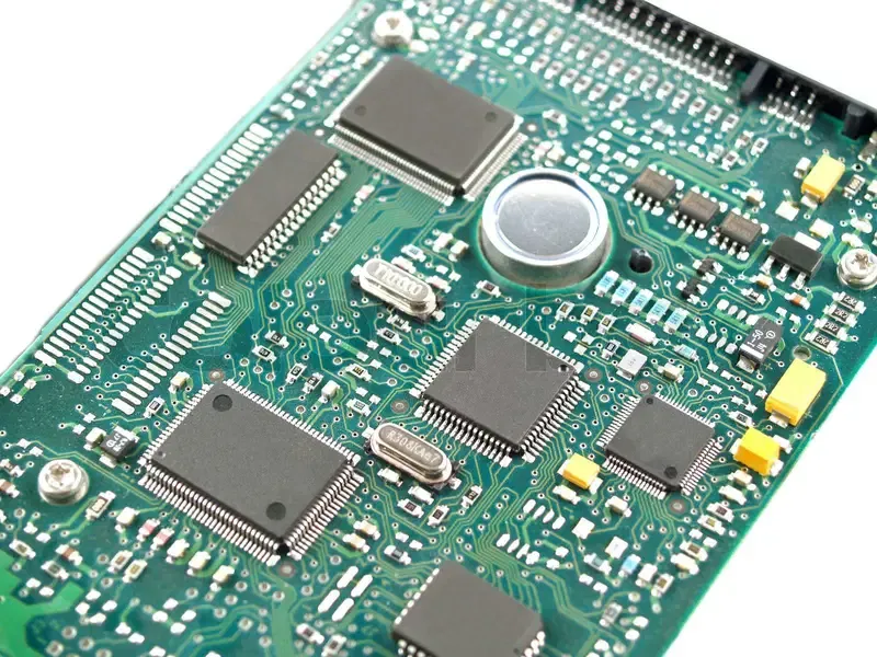
Identifying Components on an ECU PCB
Accurately identifying each component on an ECU PCB is a critical and often meticulous phase. Knowing the function of each part is key to deciphering the overall circuit operation.
Common Component Recognition Strategies
● Resistors and Capacitors: Examine resistors for their color bands to determine resistance values (e.g., a 1kΩ resistor), or look for numerical markings on capacitors (e.g., 10uF). If markings are unclear, confirm values with a multimeter.
● Integrated Circuits (ICs): Record the part numbers printed on ICs and search online databases for their datasheets. These datasheets provide detailed information on pin assignments, internal architecture, and functional characteristics (e.g., an "MC9S12" might be a specific microcontroller with defined pin functions).
● Diodes and Transistors: Note any polarity indicators on diodes and determine the type of transistor (NPN or PNP) using your multimeter's testing modes.
● Connectors: Systematically trace where each connector leads. This helps determine its purpose, such as connecting to engine sensors, the vehicle's Controller Area Network (CAN) bus, or other external interfaces.
If a component's identity remains elusive, careful desoldering for closer inspection might be necessary, but this should be considered a last resort to prevent potential damage to the board.
Reconstructing ECU PCB Schematics
Once the layout is understood and components are identified, the pivotal step is recreating the schematic diagram. This electrical blueprint illustrates how every component is interconnected.
Step-by-Step Schematic Generation
1. Establish Power and Ground: Begin by drawing the primary power supply lines and ground connections. These form the fundamental electrical pathways upon which the rest of the circuit is built.
2. Map Component Interconnections: Employ a multimeter in continuity mode to trace connections between individual components. For instance, confirm if a specific resistor links to a particular pin of an integrated circuit.
3. Illustrate Signal Flow: Identify and trace the pathways of input and output signals, such as sensor data flowing into the microcontroller or control signals directed to actuators. These are typically carried by thinner traces.
4. Utilize Software Tools: Transfer all findings into dedicated schematic drawing software. This allows for the creation of a clean, organized, and easily readable circuit diagram. Ensure every connection and component is clearly labeled.
For intricate multi-layer boards, advanced techniques like X-ray imaging can be invaluable for revealing hidden internal traces. As a destructive last resort, carefully sanding down layers might expose internal wiring, though this irreversibly alters the board.
Validating the Reverse-Engineered ECU Design
After creating the schematic, validating its accuracy is paramount. This involves testing the actual ECU PCB to ensure your reconstructed diagram correctly reflects its operational behavior.
Testing and Verification Procedures
Reconnect the ECU to a power source (only if absolutely certain it is safe to do so) and use an oscilloscope to measure signals at key test points. For example, verify if the clock signal on a microcontroller pin matches the expected frequency documented in its datasheet (e.g., 8MHz). Compare these live measurements with the expectations derived from your schematic to confirm accuracy.
Should any discrepancies emerge, meticulously revisit your documentation, component identifications, and trace mappings to pinpoint and rectify errors. This iterative process of drawing, testing, and refining ensures your reverse-engineered schematic is as precise as possible, closely mirroring the original design.
Ethical and Legal Considerations in Automotive Electronics Reverse Engineering
Engaging in the reverse engineering of an ECU PCB, especially for commercial or unauthorized purposes, can venture into complex ethical and legal territory. It is imperative to always operate within established boundaries.
Guiding Principles
● Intellectual Property (IP) Rights: Respect existing intellectual property laws. Avoid using reverse-engineered designs for unauthorized replication, commercial production, or profit generation without explicit permission.
● Regulatory Compliance: Ensure all activities adhere to local laws governing automotive electronics, vehicle modifications, and intellectual property.
● Purpose of Work: Primarily engage in reverse engineering for educational enrichment, legitimate repair tasks, or personal projects that fall within legal confines.
Overcoming Challenges in ECU PCB Reverse Engineering
Reverse engineering an ECU PCB is a demanding task, often presenting various obstacles. Awareness of these common hurdles, along with proactive strategies, can significantly improve the chances of success.
Navigating Common Difficulties
● Multi-Layer Board Complexity: Internal layers pose a significant challenge, as their traces are invisible from the surface. While X-ray imaging is ideal for non-destructive analysis, focusing on externally accessible connections and making educated inferences can still yield substantial progress.
● Obscured Component Markings: Components with deliberately erased or faded markings can be identified by analyzing their electrical characteristics using a multimeter, comparing observed behavior against known component types.
● Firmware Analysis: Although this guide emphasizes hardware, ECUs are heavily reliant on embedded firmware. Analyzing or extracting this code introduces another layer of complexity, often requiring specialized skills in programming, debugging, and potentially cryptography.
Practical Tips for Effective Automotive PCB Reverse Engineering
To conclude, here are some practical recommendations to streamline and enhance your reverse engineering efforts, fostering a more successful and insightful experience.
Best Practices for Success
● Methodical Documentation: Maintain meticulous records of every step. Comprehensive documentation prevents confusion, aids in tracing complex connections, and simplifies the review process.
● Incremental Approach: Begin by analyzing simpler, more isolated sections of the PCB, such as power supply circuits, before attempting to tackle highly complex areas like the microcontroller and its associated peripherals.
● Community Engagement: Actively participate in online forums and specialized communities focused on automotive electronics. These platforms are invaluable sources of shared knowledge, advice, and collaborative problem-solving.
● Skill Development: Practice your reverse engineering techniques on less critical or discarded PCBs. This allows you to hone your skills and build confidence before working on a valuable or irreplaceable ECU.
Conclusion: Mastering the Art of ECU PCB Reverse Engineering
Reverse engineering an ECU PCB is a profoundly rewarding yet challenging endeavor, offering an unparalleled deep dive into the sophisticated world of automotive electronics. By systematically following the steps outlined in this guide—from deciphering the ECU PCB layout and precisely identifying components to meticulously recreating schematics—you gain the ability to fully uncover the design and operational logic of an engine control unit.
Whether your primary objective is to carry out repairs, implement performance modifications, or conduct in-depth research, a disciplined and methodical approach, combined with the appropriate tools, will pave your way to success in automotive PCB reverse engineering. Always prioritize safety, strive for accuracy in every detail, and remain cognizant of ethical considerations throughout your project. With perseverance and consistent practice, you will cultivate invaluable insights into the intricate design and sophisticated functionality of ECUs.


