Why Construct a DIY Soil Moisture Sensor?
Soil moisture sensors are indispensable instruments for cultivators, gardeners, and anyone involved in agricultural practices. They provide crucial data on the soil's water content, helping to ensure plants receive optimal hydration. While commercial sensors are readily available, embarking on a DIY soil moisture sensor project offers distinct advantages.
This approach is notably cost-effective, as creating your own sensor with a custom PCB can be significantly less expensive than purchasing pre-manufactured units. Furthermore, it allows for customization, enabling you to tailor the design to meet specific requirements, such as seamless integration with an Arduino for automated irrigation systems. Beyond practical benefits, this project serves as an excellent learning opportunity, providing hands-on experience in electronics, home PCB etching, and programming. By focusing on DIY soil moisture sensor projects and custom PCB design, this guide aims to empower you to develop personalized agricultural monitoring solutions.
Essential Materials for This Agricultural Electronics Project
Before commencing construction, it is imperative to gather all necessary components and tools for assembling your Arduino soil sensor with a fast turn custom PCB. A comprehensive list is provided below to ensure a smooth workflow:
● Microcontroller: An Arduino board (e.g., Uno or Nano) will serve as the brain for processing sensor data.
● Sensor Components: For a capacitive sensor, copper traces on the PCB itself will be key. If opting for a resistive design, stainless steel probes or graphite rods will be required.
● PCB Fabrication Materials: You'll need a blank copper-clad board, ferric chloride for the etching process, and appropriate PCB design software for creating the layout.
● Electronic Components: Specific resistor and capacitor values will depend on your circuit design, but typically include 10kΩ resistors for voltage dividers.
● Soldering Toolkit: Essential items include a soldering iron, solder wire, and a multimeter for verifying electrical connections.
● Interconnects: Wires and connectors are needed to link the custom PCB to the Arduino and the sensing probes.
● Protective Measures: A waterproof sealant or epoxy is crucial for protecting the PCB from moisture ingress in its operational environment.
● Software: A free PCB design tool (such as Fritzing or KiCad) and the Arduino IDE for programming the microcontroller.
Having these materials prepared in advance will significantly streamline the process of building your DIY soil moisture sensor and ensure a more efficient experience during custom PCB design and PCB etching at home.
How Do Soil Moisture Sensors Function?
Soil moisture sensors gauge the water content within the soil by detecting variations in its electrical properties. Two prevalent types are commonly employed in DIY projects:
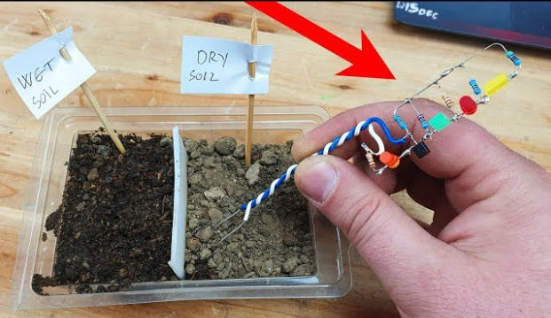
● Resistive Sensors: These devices quantify the electrical resistance between two probes embedded in the soil. Wetter soil, being more conductive, exhibits lower resistance (typically ranging from 300-700 ohms), whereas dry soil presents higher resistance (exceeding 1000 ohms).
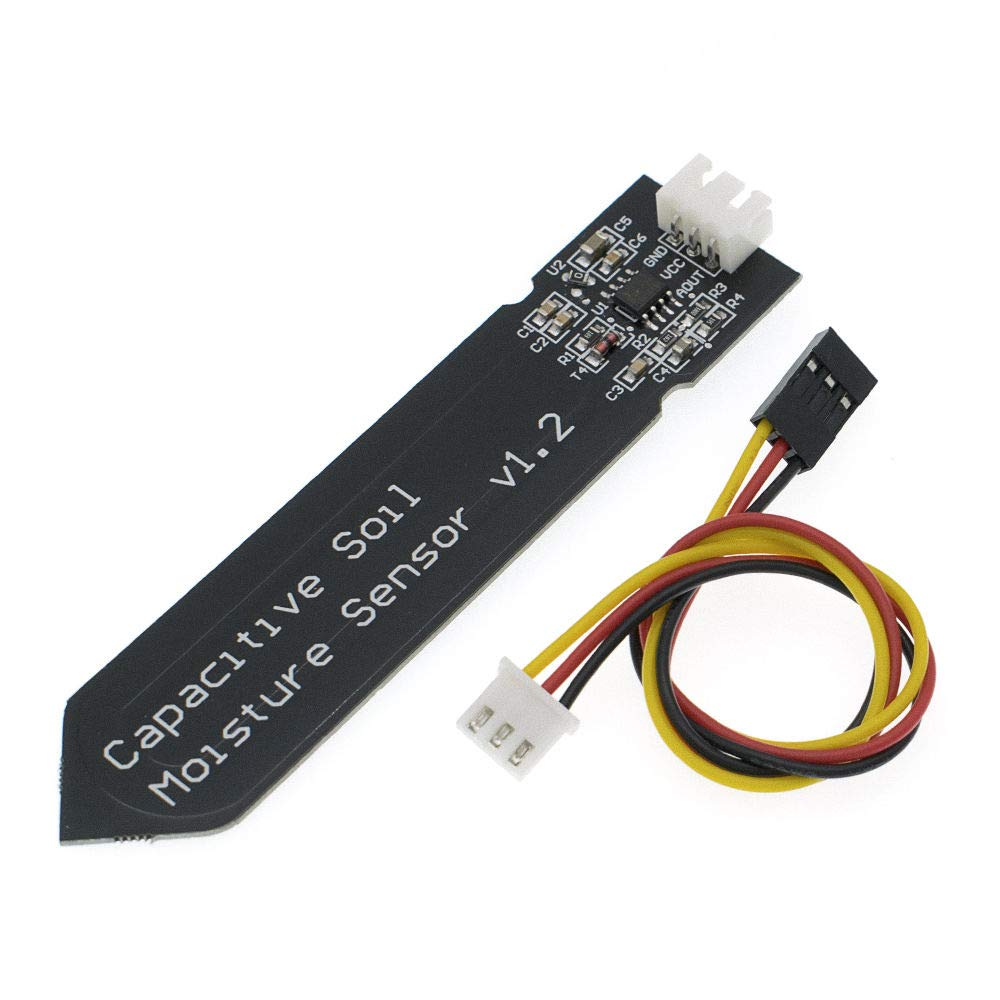
● Capacitive Sensors: Utilizing the soil as a dielectric medium between two conductive plates, these sensors measure changes in capacitance. Increased soil moisture elevates capacitance (often within the 300-500 pF range), while dry conditions reduce it.
For the purpose of this DIY soil moisture sensor project, we will concentrate on a capacitive design. This choice is primarily due to its enhanced durability and superior resistance to corrosion when compared to resistive sensor types. The capacitive sensor will interface with an Arduino, which will then translate the analog readings into meaningful data for continuous soil condition monitoring.
Step 1: Crafting Your Custom PCB Design for the Sensor
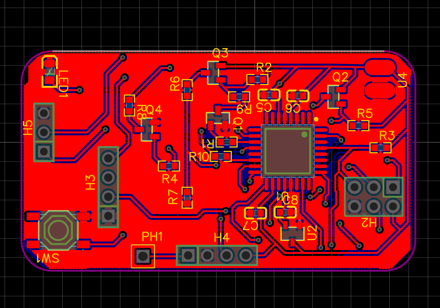
The foundational step in constructing your Arduino soil sensor involves developing a custom PCB design. This board will integrate the capacitive sensor's circuitry and facilitate its connection to the Arduino.
Begin by selecting a PCB design software, ideally a free tool, to create your circuit schematic. For a capacitive sensor, draw a straightforward circuit where two copper traces function as the capacitive plates. These traces will either connect to an oscillator circuit or directly to the Arduino’s analog input pins via a voltage divider. Carefully design the layout with two parallel copper traces, approximately 2-3 mm apart, on one side of the board to form the sensing elements. Ensure ample space is allocated for soldering connections to the Arduino. Once the schematic and layout are complete, export the design as a printable file suitable for etching. The traces should be sufficiently wide (at least 1 mm) to guarantee durability and robust performance. This custom PCB design phase is paramount for this agricultural electronics project, directly influencing the accuracy and longevity of your DIY soil moisture sensor.
Step 2: Performing PCB Etching at Home
Once your PCB design is finalized, the next exciting stage is performing PCB etching at home. This process precisely transfers your digital design onto a copper-clad board by chemically removing unwanted copper.
First, print the design using a laser printer onto glossy paper or a transparency film. Verify that the design is mirrored if your chosen transfer method requires it. Next, transfer the design by carefully placing the printed layout onto the copper-clad board. Use a hot iron to firmly press and transfer the toner onto the copper, applying even pressure for approximately 5-10 minutes. Following this, etch the board by submerging it in a ferric chloride solution. Always adhere to safety instructions and wear appropriate protective gear. Agitate the solution gently for 10-20 minutes until all unprotected copper has dissolved, leaving only your desired circuit traces. Finally, clean and drill the board: remove the remaining toner with acetone or rubbing alcohol, then use a small drill bit (0.8-1 mm) to create holes for component mounting. Home PCB etching can be a highly satisfying aspect of building your DIY soil moisture sensor, granting you complete autonomy over your hardware's physical design. Always conduct etching in a well-ventilated area and ensure responsible disposal of all chemicals.
Step 3: Assembling the Sensor Circuit onto the PCB
With your custom HDI PCB successfully etched, the next phase involves assembling the necessary components. For a capacitive soil moisture sensor, the PCB itself, specifically its copper traces, serves as the primary sensing element.
Begin by soldering connections to the copper traces on the PCB. These wires will connect to the Arduino’s analog input pins, typically through a simple RC (resistor-capacitor) circuit designed to measure changes in capacitance. After soldering, apply a protective coating—such as a waterproof sealant or epoxy—over the entire PCB, deliberately leaving the sensing traces exposed. This coating is crucial for shielding the board's electronics from environmental moisture while allowing the exposed traces to interact with and detect soil conditions. Conclude this step by testing the circuit with a multimeter to confirm continuity and rule out any short circuits. In dry conditions, you might observe typical capacitance values around 100 pF, which should increase to approximately 400-500 pF when the sensor is placed in wet soil. This assembly process ensures that your custom PCB design effectively functions as a dependable Arduino soil sensor for various agricultural applications.
Step 4: Programming the Arduino for Moisture Data
Once your sensor hardware is complete, the next crucial step is to program the Arduino to interpret data from your DIY soil moisture sensor. This involves a basic approach using a capacitive sensing method.
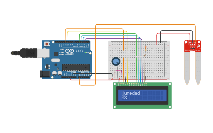
Begin by connecting the sensor: wire the PCB traces to an analog input pin on the Arduino (e.g., A0) via a resistor (e.g., 1 MΩ). This setup creates a simple timing circuit where the resistor and the soil's capacitance determine a charge/discharge time. Next, write the code using the Arduino IDE. Your sketch will measure the time it takes for the capacitor (formed by the soil between the traces) to charge and discharge. Longer charge times will indicate higher capacitance, signifying wetter soil. Finally, calibrate the sensor by testing it in both completely dry and saturated soil samples to establish baseline values. For instance, dry soil might yield an analog reading of 100-200, while saturated soil could read 600-800 on the Arduino’s 0-1023 scale.
You will need to adjust this code based on your specific calibration data to accurately map the raw sensor readings to meaningful percentage moisture levels. This programming phase fully integrates your custom PCB design with the Arduino, transforming it into a functional soil sensor.
Step 5: Testing and Deploying Your Soil Moisture Sensor
Before integrating your newly built sensor into a live agricultural environment, it is essential to conduct thorough testing.
Perform initial testing by inserting the sensor into various soil samples—dry, moist, and wet—and carefully monitor the readings displayed on the Arduino Serial Monitor. Ensure that the values consistently change in a predictable manner corresponding to the different moisture levels. Follow this with long-term testing; position the sensor outdoors in a garden or a potted plant for several days to assess its durability and consistency under real-world conditions. Remember to protect the Arduino board and all electrical connections from weather elements using a robust, weatherproof enclosure. Finally, consider integration by programming the Arduino to trigger specific actions. For example, the sensor data could activate a water pump if the detected soil moisture drops below a predetermined threshold (e.g., 30%, based on your calibration data). This electronics project for agriculture offers potential for expansion, such as adding wireless communication capabilities or connecting multiple sensors for large-scale monitoring systems.
Enhancing Your DIY Soil Moisture Sensor's Performance
To significantly improve both the performance and longevity of your Arduino soil sensor, consider incorporating these valuable tips into your design and maintenance routine.
Firstly, always utilize high-quality materials, opting for corrosion-resistant coatings and robust PCB substrates that can withstand challenging outdoor conditions. Secondly, implement regular calibration practices; recalibrate the sensor every few months, as natural soil property changes or sensor wear can gradually impact reading accuracy. Thirdly, strive to minimize electromagnetic interference by positioning the sensor away from large metal objects or active power lines, which could disrupt capacitance measurements. By adopting these improvements, your DIY soil moisture sensor will consistently deliver accurate and reliable data for agricultural applications.
Conclusion: Begin Your Arduino Soil Sensor Project Today
Embarking on the creation of a DIY soil moisture sensor with a custom PCB is an incredibly rewarding electronics project for agriculture, seamlessly blending technical ingenuity with practical application. By meticulously following the outlined steps—from designing a custom PCB and executing home etching, to assembling the circuit, programming an Arduino, and rigorously testing the sensor—you will equip yourself with a potent tool for precisely monitoring soil conditions.
This project offers more than just cost savings; it provides invaluable insights into the intricacies of custom PCB design and Arduino integration. Whether you are taking your first steps into electronics or are an experienced maker, the competencies acquired through PCB etching at home and constructing an Arduino soil sensor will unlock opportunities for pursuing more complex and advanced projects.
Initiate your journey today by exploring the vast resources and tools available for custom PCB design. With a well-thought-out approach, your DIY soil moisture sensor will become an indispensable asset, helping to optimize water usage and promote healthier plant growth in any agricultural setting.


