Why Create a DIY Smart Meter PCB for Home Energy Monitoring?
Are you interested in constructing a DIY smart meter PCB to precisely track your home energy consumption? This comprehensive guide will navigate you through the entire process of developing your own energy monitoring system, from conceptualizing the smart meter PCB schematic to the final programming of the device. Whether you're an electronics enthusiast or a seasoned engineer, you'll find practical, actionable steps for a successful DIY smart meter PCB project. This includes crucial advice on schematic design, physical layout, component acquisition, and software development. Let’s delve into the specifics of building a system capable of accurately monitoring and managing your electricity usage.
The Advantages of Building Your Own Smart Meter PCB
Smart meters are increasingly recognized as indispensable tools for effectively managing energy consumption in both residential and small business settings. Unlike conventional meters, a smart meter delivers real-time data on electricity usage, empowering you to pinpoint inefficiencies and realize cost savings on your utility bills. While a wide array of commercial smart meters are readily available, embarking on your own DIY smart meter PCB project offers distinct benefits:
● Cost-Effectiveness: Developing your own system can prove more economical than purchasing a pre-assembled device, particularly if you already possess some of the necessary electronic components.
● Tailored Customization: You gain the flexibility to customize the design and features to align perfectly with your unique requirements, such as seamless integration with existing home automation platforms.
● Invaluable Learning Opportunity: The process of designing and assembling a smart meter PCB provides an excellent avenue for deepening your understanding of electronics and the principles of energy monitoring.
In this guide, we will explore every facet of constructing a smart meter PCB, providing you with a clear, step-by-step roadmap for creating your personalized energy monitoring system.
Fundamental Concepts of a Smart Meter PCB
Before commencing your DIY smart meter PCB project, it’s essential to grasp the core functions of a smart meter and the key components involved. A smart meter's primary role is to measure various electrical parameters—such as voltage, current, and power consumption—then process, display, or transmit this data for subsequent analysis.
The fast turn PCB serves as the central hub of any smart meter, integrating essential sensors, microcontrollers, and communication modules. Here’s a brief overview of the critical functionalities your PCB design should facilitate:
● Accurate Measurement: The ability to precisely capture voltage and current data through dedicated sensors.
● Data Processing: Employing a microcontroller to compute crucial metrics like power and cumulative energy usage.
● Seamless Communication: Transmitting collected data to a display unit or an external system via protocols such as Wi-Fi, Bluetooth, or other relevant standards.
● Intuitive User Interface: Providing a means for users to view data, whether through an integrated LCD screen or a compatible smartphone application.
With these foundational principles in mind, let’s advance to the crucial stage of designing the smart meter PCB schematic.
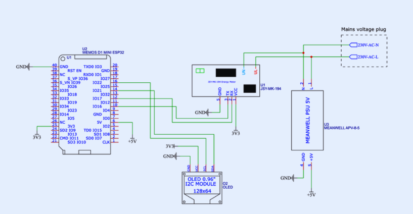
Step 1: Developing Your Smart Meter PCB Schematic
The smart meter PCB schematic acts as the foundational blueprint for your entire project, meticulously defining how each component is interconnected to ensure the system operates precisely as intended. For a successful DIY smart meter PCB project, your schematic design must prioritize several key elements.
Essential Components for Your Schematic
Your schematic should incorporate the following critical components:
● Current Sensor: A non-invasive current sensor, such as a current transformer (CT) paired with a burden resistor, is vital for safely measuring AC current. For example, a CT sensor with a 100A:50mA ratio is highly effective for monitoring typical household electrical loads.
● Voltage Sensor: A voltage divider circuit or a specialized voltage sensor module is required to accurately measure AC voltage. This component typically steps down household voltages (e.g., 220V or 110V) to a safe level, such as 5V, suitable for the microcontroller’s input.
● Microcontroller: A widely supported option like the ESP32 or an Arduino board is an excellent choice, capable of processing sensor data and managing communication. The ESP32, for instance, features integrated Wi-Fi, making it ideal for remote energy monitoring applications.
● Power Supply: A dedicated circuit to convert AC input into stable DC power (e.g., 5V or 3.3V) is necessary to energize the microcontroller and all other active components. A 5V 1A power module is often sufficient for most designs.
● Communication Module: If you're not using a microcontroller with integrated communication capabilities (like the ESP32), you may need to add a separate Wi-Fi or Bluetooth module for data transmission.
● Display (Optional): For local real-time data visualization, an OLED or LCD screen, such as a 0.96-inch OLED with I2C communication, can be incorporated.
Constructing the Schematic
Begin by using a free or open-source electronic design automation (EDA) tool to draw your smart meter PCB schematic. Position the microcontroller centrally within your design, then systematically connect the various sensors, power supply, and communication modules around it. Ensure proper grounding techniques are applied throughout the schematic to mitigate noise in measurements, and include any necessary resistors and capacitors for effective signal conditioning. For example, a 10kΩ resistor within a voltage divider circuit is crucial for accurately scaling down high voltages for the microcontroller’s analog-to-digital converter.
Step 2: Developing the Smart Meter PCB Layout
Once your schematic is finalized, the subsequent critical phase in your DIY smart meter PCB project involves designing the physical PCB layout. The smart meter PCB layout dictates the precise physical arrangement of components and the routing of conductive traces across the board, which directly influences the system's performance and overall safety.
Strategies for an Effective PCB Layout
● Optimized Component Placement: Strategically place high-voltage components, particularly those associated with AC sensors, at a safe distance from low-voltage sections to prevent electrical interference. Keep the microcontroller in close proximity to the communication and display modules to ensure shorter, more efficient signal paths.
● Appropriate Trace Width: Utilize wider traces for all high-current paths, especially in the vicinity of the power supply unit. For example, a trace designed to carry 1A at 5V should have a minimum width of 0.5mm to prevent overheating and ensure stability.
● Robust Ground Plane: Incorporate a solid ground plane throughout the design to significantly reduce electrical noise and enhance signal integrity. This is particularly important for achieving accurate and reliable sensor readings.
● Enhanced Isolation: Ensure ample isolation between AC and DC sections to uphold safety standards. A minimum clearance of 3mm between high-voltage and low-voltage traces is highly recommended for applications within typical household electrical systems.
Upon completion of the layout, conduct a thorough review for potential errors such as overlapping traces or unconnected pins. Most EDA tools are equipped with design rule check (DRC) functionalities to help identify and rectify these issues before proceeding to manufacturing.
Step 3: Smart Meter PCB Component Acquisition
Sourcing the right components for your DIY smart meter PCB project is a pivotal stage that directly impacts both the final cost and the performance of your system. You’ll need to identify reputable suppliers and ensure that all selected components strictly adhere to your schematic's specifications.
Reliable Component Sourcing Channels
Look for components from well-established online marketplaces or specialized local electronics retailers. Reputable platforms typically offer a broad selection of sensors, microcontrollers, and other essential parts at competitive prices. Here are some key recommendations for smart meter PCB component sourcing:
● Current and Voltage Sensors: Acquire CT sensors and voltage modules that are explicitly rated for your household’s electrical system (e.g., a current rating of 100A and a voltage rating of 250V).
● Microcontrollers: Opt for widely supported development boards such as the ESP32, which typically costs around $5–10 and benefits from a vast online community for support and troubleshooting.
● Passive Components: Resistors, capacitors, and diodes can often be purchased in bulk, leading to significant cost savings. For instance, a pack of 100 10kΩ resistors might cost less than $2.
● Power Supply Modules: Select a power module that includes overcurrent protection to safeguard your circuit; these modules are generally priced between $1–3 each.
Ensuring Component Quality
Always review the component datasheets to confirm that they fully meet your design requirements. For example, verify that the current sensor’s output range (e.g., 0–5V) is compatible with your microcontroller’s analog input pins. Purchasing from reputable suppliers significantly reduces the risk of acquiring counterfeit or substandard parts.
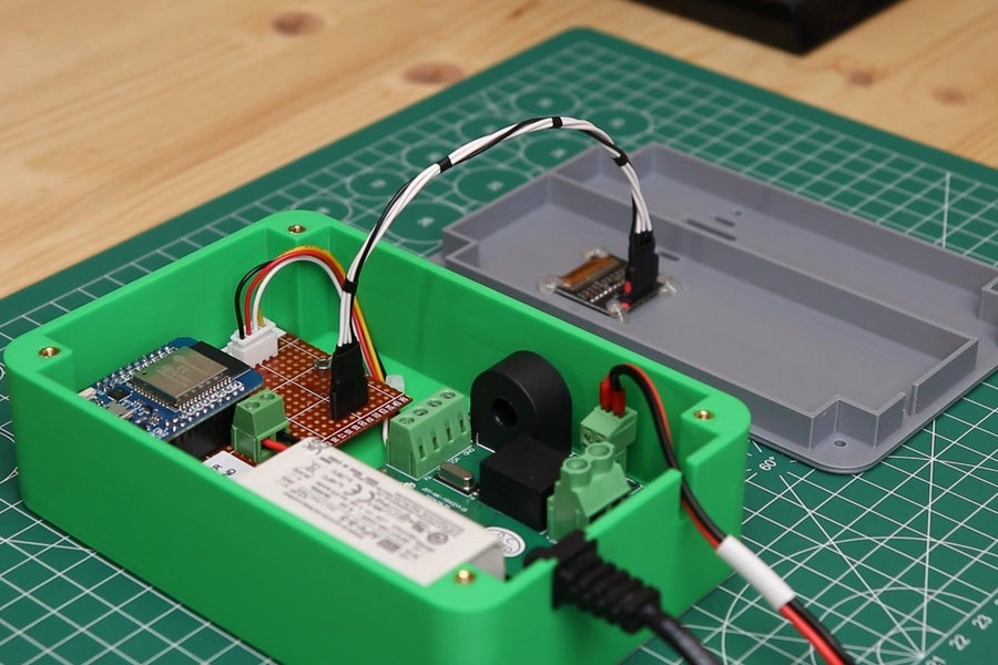
Step 4: Assembling Your Smart Meter PCB
With your PCB manufactured and all components successfully sourced, the next critical step is to assemble your smart meter PCB. This phase demands fundamental soldering proficiency and meticulous attention to detail to prevent potential errors.
Key Assembly Tips
● Begin with Smaller Components: Start by soldering smaller components such as resistors, capacitors, and similar passive parts, then progressively move on to larger items like sensors and microcontrollers.
● Verify Polarity: Ensure the correct orientation for all polarized components, including diodes and electrolytic capacitors, to prevent damage or malfunction.
● Test Connections Thoroughly: After each soldering session, use a multimeter to verify all connections, meticulously checking for any short circuits or open connections.
● Prioritize Safety: Given that this project involves AC power, it is imperative to insulate any exposed high-voltage areas using heat shrink tubing or high-quality electrical tape.
Once the assembly is complete, perform a thorough visual inspection of the board to identify any cold solder joints or incorrectly placed components before applying power.
Step 5: Smart Meter PCB Programming
Programming is the crucial penultimate step in bringing your DIY smart meter PCB project to life. The core objective of smart meter PCB programming is to accurately read sensor data, compute energy usage metrics, and then transmit or display these results effectively.
Fundamental Programming Concepts
If you are utilizing a microcontroller like the ESP32, you can program it efficiently using an integrated development environment (IDE) such as the Arduino IDE. Here’s a streamlined workflow for smart meter PCB programming:
● Read Sensor Data: Develop code to acquire analog signals from both the current and voltage sensors. For instance, leverage the ESP32’s analog-to-digital converter (ADC) pins to capture voltage levels.
● Calculate Power: Multiply instantaneous voltage and current readings to determine power in watts. Integrate this power over time to calculate cumulative energy usage in watt-hours. A typical household might consume an average of 500W, so ensure your code is designed to accurately handle such values.
● Transmit Data: Utilize Wi-Fi libraries to dispatch the collected data to a cloud server or a local application. Libraries like "ESPAsyncWebServer" can facilitate the creation of a web interface for remote monitoring.
● Display Results: If you’ve included a local display, program it to update with real-time readings every few seconds, possibly using a library such as "Adafruit_GFX" for OLED screens.
Illustrative Code Snippet
Here is a basic example demonstrating how to read sensor data using an ESP32:
codeC++
const int currentPin = 34; // Analog pin for current sensor
const int voltagePin = 35; // Analog pin for voltage sensor

void setup() {
  Serial.begin(115200);
}

void loop() {
  int currentValue = analogRead(currentPin); // Read current sensor raw value
  int voltageValue = analogRead(voltagePin); // Read voltage sensor raw value

  // Convert raw ADC readings to actual voltage values (assuming 0-5V range for ADC)
  float current = currentValue * (5.0 / 4095.0);
  float voltage = voltageValue * (5.0 / 4095.0);

  float power = current * voltage; // Calculate instantaneous power

  Serial.print("Power: ");
  Serial.println(power);
  delay(1000);
}
This code serves as a foundational starting point. You will need to calibrate the sensor readings based on your specific sensor specifications and integrate additional features such as data logging, remote access, or advanced data visualization.
Step 6: Thorough Testing and Calibration
After completing the programming, it is crucial to rigorously test your smart meter PCB to confirm its accurate operation. Connect the system to a known electrical load, such as a 100W incandescent bulb, and carefully compare its readings against those from a reliable reference meter. If you observe any discrepancies, adjust your code's calibration factors or sensor parameters accordingly. For instance, if your current sensor consistently overreads by 5%, you might apply a correction factor by multiplying its readings by 0.95 within your code.
Furthermore, comprehensively test the communication functionalities. Verify that data is transmitted accurately and promptly to your designated application or server, free from noticeable delays. Ensure the entire system maintains stable operation over extended periods, as continuous energy monitoring requires unwavering reliability.
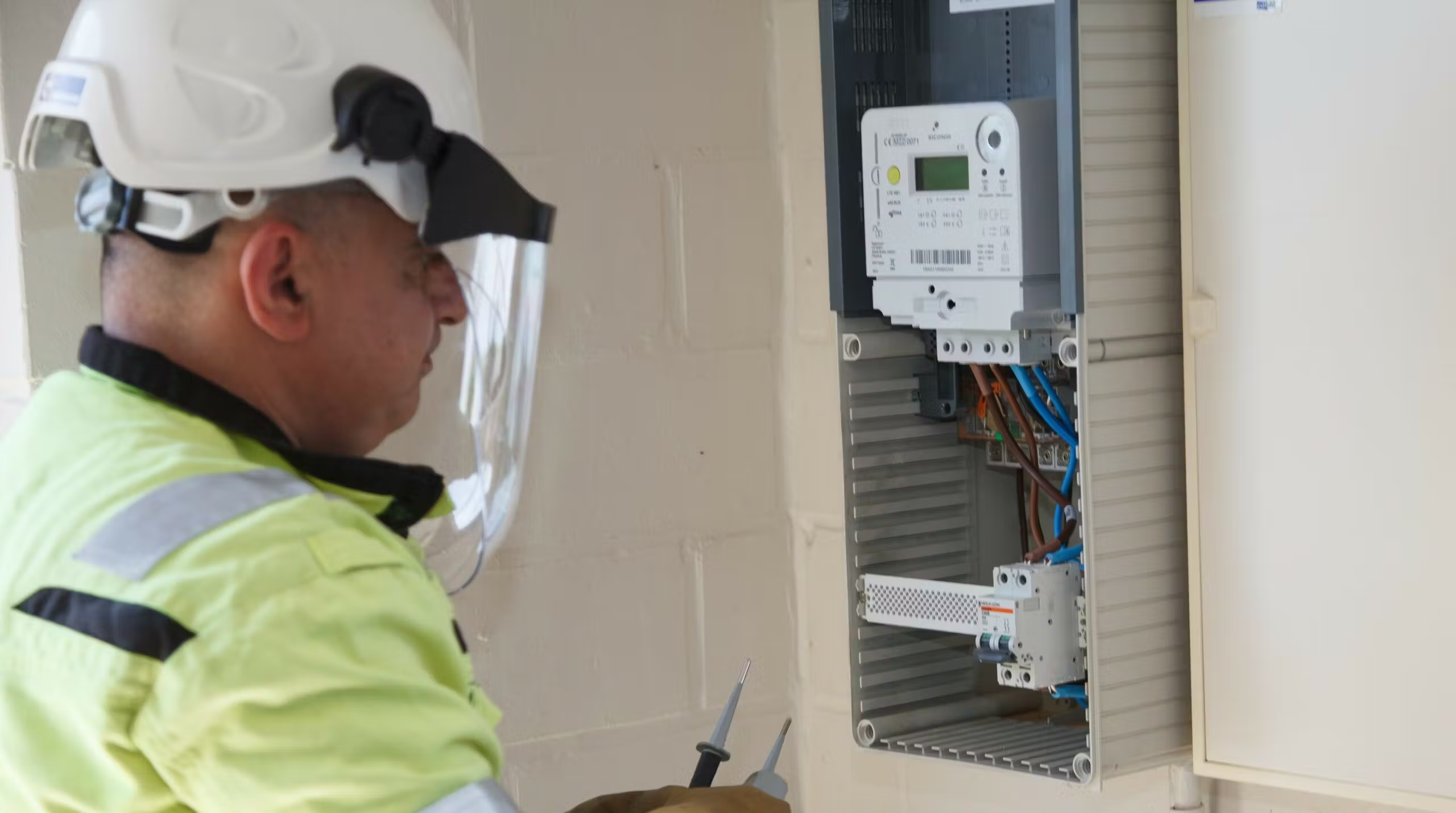
Step 7: System Integration and Safe Installation
Finally, the culminating step involves integrating your DIY smart meter PCB into your home’s existing electrical infrastructure. Install the device in close proximity to your main power line, utilizing a non-invasive CT sensor clamped securely around the live wire. Mount the PCB within a protective enclosure to shield it from dust, moisture, and accidental physical contact. If you lack experience with electrical installations, it is strongly advised to consult a certified professional electrician to mitigate any potential safety hazards.
For a comprehensive and fully integrated energy monitoring system, consider connecting your smart meter to a broader home automation platform. This integration will enable you to meticulously track usage patterns, configure alerts for periods of high consumption, and ultimately maximize the benefits derived from your DIY project.
Conclusion
Building a DIY smart meter PCB is an immensely rewarding endeavor, synergizing electronics design, programming, and practical real-world application. By diligently following the sequential steps outlined in this guide—from meticulously designing the smart meter PCB schematic, crafting an efficient layout, carefully sourcing components, through PCBA assembly, programming, and rigorous testing—you can successfully create a bespoke energy monitoring system tailored precisely to your individual requirements. Not only will you cultivate invaluable technical skills, but you will also gain unprecedented control over your energy consumption, potentially realizing significant long-term financial savings.
With the appropriate tools and unwavering dedication, your DIY smart meter PCB project can serve as an excellent stepping stone towards developing more sophisticated home automation solutions. Start with manageable steps, test thoroughly at each stage, and thoroughly enjoy the process of creating a system that is both highly functional and truly innovative.


