Why Embark on a Custom PCB Heart Rate Monitor Project?
Constructing a heart rate monitor offers an excellent entry point for electronics novices. This endeavor uniquely integrates sensor technology, microcontroller programming, and fundamental PCB design into a single, immersive learning experience. Opting for a custom PCB over a breadboard solution yields a more compact, robust, and professional-looking device. Moreover, mastering skills like DIY PCB fabrication and soldering components directly opens avenues to more intricate and ambitious projects. This guide is specifically tailored for individuals new to electronics but eager to delve into a rewarding heart rate monitor PCB project.
Essential Components and Tools for This Project
Before commencing, it’s beneficial to assemble all required tools and components. Having everything prepared ensures a smoother and more enjoyable construction process.
● Arduino Board: A microcontroller, such as the Arduino Uno, to process data from the sensor.
● Heart Rate Sensor: A pulse sensor module, typically an optical sensor, for detecting heartbeats.
● Passive Components: Resistors and capacitors for signal filtering and stabilization (e.g., 1kΩ resistors and 0.1μF capacitors, as will be detailed later).
● Output Devices (Optional): An LED or a small OLED display for visual feedback of heart rate data.
● PCB Fabrication Materials: A copper-clad board, ferric chloride for the etching process, and either a permanent marker or a laser printer for transferring the circuit design.
● Soldering Equipment: A soldering iron, solder wire, and flux are essential for precisely soldering components onto the PCB.
● Design Software: Free CAD tools like KiCad or Fritzing for creating your PCB layout.
● Basic Workshop Tools: A small hand drill for PCB holes, a multimeter for continuity checks, and crucial safety gear, including gloves and goggles, for PCB etching at home.
Step 1: Understanding the Mechanism of a Heart Rate Monitor
A heart rate monitor determines the number of heartbeats per minute (BPM) by sensing subtle changes in blood flow. Most entry-level sensors utilize optical principles: an integrated light source (usually an LED) illuminates the skin, and a photodiode then measures variations in light intensity caused by the pulsating blood flow. The Arduino heart rate sensor module processes this raw data and converts it into a quantifiable BPM reading.
Typically, these pulse sensors operate within a signal frequency range of 0.5Hz to 4Hz, which corresponds to heart rates between 30 and 240 BPM. The Arduino reads this incoming analog signal, applies a specific threshold or algorithm to accurately count the pulses, and subsequently outputs the computed heart rate. A clear understanding of this foundational principle is crucial for effectively designing the circuit and the PCB layout for your heart rate monitor PCB project.
Step 2: Designing the Core Heart Rate Monitor Circuit
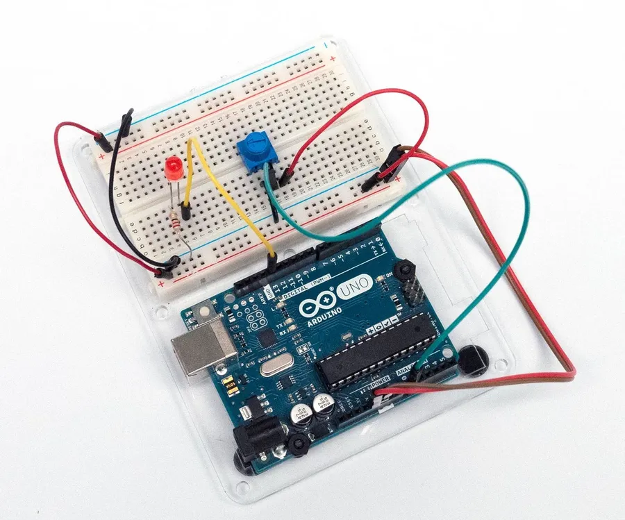
Begin by crafting a straightforward circuit that links the heart rate sensor to your Arduino. The typical sensor module features three pins: VCC (power, usually 3.3V or 5V), GND (ground), and Signal (analog output). Connect VCC to the Arduino’s 5V pin, GND to the Arduino’s GND, and the Signal pin to an analog input, such as A0.
To enhance signal clarity and reduce noise, incorporate a simple RC filter. This involves placing a 1kΩ resistor in series with the signal line and connecting a 0.1μF capacitor from this point to ground. This filtering arrangement helps mitigate high-frequency noise, ensuring more precise readings. Once the circuit design is finalized, it's advisable to prototype and test it on a breadboard before proceeding to the actual PCB layout.
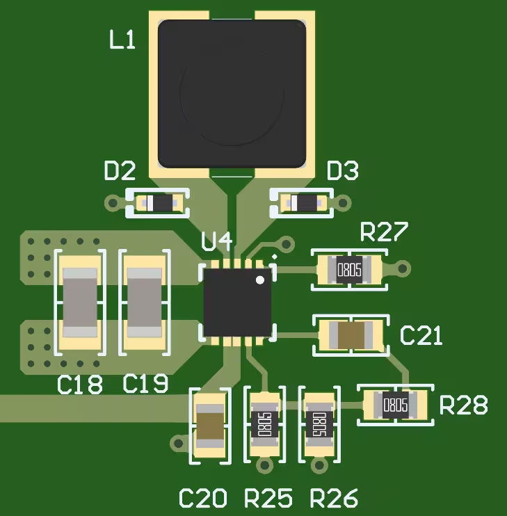
Step 3: Crafting a Custom PCB Layout
With your circuit successfully validated on a breadboard, the next phase involves DIY PCB fabrication. Designing a custom PCB provides superior durability and a more compact form factor for your project. Follow these steps to generate your PCB layout:
● Select Design Software: Utilize a free, open-source tool like KiCad to first draw your circuit schematic and then convert it into a PCB layout. Strategically position the Arduino, sensor, and all passive components to minimize trace lengths.
● Define Traces and Pads: Ensure that all traces are sufficiently wide (at least 0.25mm) to carry the expected current without risk of breakage. Maintain clear separation between power and ground traces to prevent unwanted interference.
● Export the Final Design: Once your PCB layout is complete, print it onto glossy paper using a laser printer, or meticulously draw the design directly onto the copper board with a permanent marker for manual transfer.
The primary objective is to create a clean, functional design that efficiently interconnects all components. For those new to PCB design, simplicity is key; consider starting with a single-layer board for this heart rate monitor PCB project.
Step 4: Performing PCB Etching at Home
PCB etching at home offers an economical method for creating custom circuit boards without requiring expensive specialized equipment. Here’s a guide to performing it safely and effectively:
● Prepare the Copper Board: Begin by thoroughly cleaning a copper-clad board using fine steel wool to remove any surface oxidation. This step is critical for ensuring that the toner or marker adheres properly.
● Transfer the Circuit Design: If using a laser printer method, carefully iron the printed design onto the cleaned copper circuit board. For manual designs, draw the circuit traces directly onto the copper using a permanent marker. The areas covered by toner or marker will protect the copper during the etching process.
● Etch the Board: Prepare a ferric chloride solution (always strictly follow the safety instructions provided on the packaging) in a plastic container. Submerge the prepared copper board into the solution for approximately 10-20 minutes, agitating the container gently and occasionally. The unprotected copper will gradually dissolve, leaving behind your meticulously designed circuit traces.
● Clean and Drill: After etching, thoroughly rinse the board with water. Remove the remaining toner or marker with acetone. Finally, use a small hand drill (bits typically ranging from 0.8mm to 1mm are suitable for most components) to create holes for all your components.
Safety is paramount during PCB etching at home. Always wear protective gloves, safety goggles, and work in a well-ventilated area to prevent any contact with the etching chemicals. Ensure responsible disposal of the spent etching solution according to local environmental regulations.
Step 5: Soldering Components onto Your Custom PCB
With your fast turn custom PCB successfully fabricated, the next step involves soldering components. Soldering might appear daunting initially, but with consistent practice, it becomes a straightforward skill. Follow these tips for achieving clean, reliable solder joints:
● Prepare Your Tools: Heat your soldering iron to approximately 300°C (572°F) for typical electronic components. Utilize a fine tip for precision work.
● Insert Components: Carefully place components through their designated drilled holes according to your PCB layout. Begin with smaller parts like resistors and capacitors before proceeding to larger components such as the sensor module.
● Execute Solder Joints: Apply a small amount of solder to the tip of your heated iron. Then, simultaneously touch the iron tip to both the PCB pad and the component lead. The solder should melt and flow smoothly, forming a shiny, volcano-shaped joint. Crucially, avoid applying excessive solder to prevent short circuits.
● Inspect and Test: Visually inspect all solder joints for any signs of "cold joints" (which appear dull or uneven). Use a multimeter to perform continuity checks and confirm that all electrical connections are secure and robust.
Take your time with each soldering connection, as errors can potentially damage components or the board itself. If a joint appears unsatisfactory, simply reheat it and carefully adjust. This step is absolutely critical for the reliability and long-term functionality of your heart rate monitor PCB project.
Step 6: Programming the Arduino for Heart Rate Monitoring
With the hardware now fully assembled, it’s time to program your Arduino to interpret data from the Arduino heart rate sensor. Here’s a fundamental approach to get you started:
● Install Necessary Libraries: Download a suitable pulse sensor library (readily available through the Arduino IDE’s built-in library manager) to streamline the signal processing tasks.
● Develop the Code: Adapt example code provided with the library to read analog values from the sensor’s designated pin (e.g., A0). These libraries typically incorporate algorithms to calculate BPM by accurately identifying peaks within the incoming signal waveform.
● Output the Data: Configure the Arduino to send the calculated BPM values to the Serial Monitor within the Arduino IDE, or display them directly on an OLED screen if you have integrated one into your project.
A common threshold value for reliably detecting a heartbeat peak might fall around 550-600 on the Arduino’s 10-bit analog scale (0-1023). This value should be fine-tuned through testing to achieve optimal accuracy. Upload the compiled code to your Arduino and test the setup by gently placing your finger onto the sensor.
Step 7: Thorough Testing and Troubleshooting Your Heart Rate Monitor
After completing assembly and programming, the next vital step is to comprehensively test your heart rate monitor by placing your finger on the sensor. For a resting adult, you should observe BPM readings typically between 60 and 100. If the readings are inconsistent, erratic, or entirely absent, proceed with troubleshooting using these guidelines:
● Verify Sensor Placement: Ensure the sensor maintains firm and consistent contact with your skin, ideally on a fingertip or earlobe for best results.
● Inspect All Connections: Meticulously verify every soldered joint and all wiring connections. Loose or faulty connections are a common cause of signal loss or erratic behavior.
● Adjust Code Parameters: If readings appear erratic, carefully adjust the threshold value within your Arduino code to improve the accuracy of peak detection.
● Mitigate Noise: If ambient light or physical movement is causing interference, consider shielding the sensor area or integrating a more robust filtering circuit.
Thorough testing guarantees that your heart rate monitor PCB project functions reliably before it is put into regular use.
Step 8: Advanced Enhancements for Your Heart Rate Monitor
Once your foundational monitor is operational, consider incorporating upgrades to enhance its user-friendliness or expand its feature set:
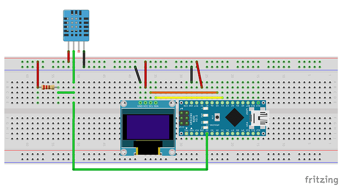
● Integrate a Display: Add a compact OLED screen to directly visualize BPM readings, eliminating the need for a connected computer.
● Bluetooth Connectivity: Incorporate a Bluetooth module to transmit heart rate data wirelessly to a smartphone application for advanced logging and analysis.
● Custom Enclosure: Design and 3D-print a protective case to shield the PCB and transform the device into a more portable unit.
These enhancements build upon the foundational skills you’ve already acquired, from DIY PCB fabrication to programming, and will help your project truly stand out.
Conclusion: Your Inaugural Journey into Custom Electronics
Constructing a heart rate monitor with a custom PCB is an exceptional method for acquiring fundamental electronics knowledge, encompassing everything from circuit design and PCB etching at home to the precise art of soldering components. This heart rate monitor PCB project not only imparts practical skills but also culminates in a functional device applicable for fitness tracking or educational exploration. By diligently following this comprehensive guide, you have successfully taken a significant step into the realm of custom electronics utilizing an Arduino heart rate sensor.
Begin with manageable steps, exercise patience throughout each phase, and you will soon be prepared to tackle more complex and challenging projects. The valuable skills you have cultivated here—circuit design, PCB creation, and programming—form the indispensable groundwork for countless future innovations. Continue to experiment, and allow your creativity to lead you through your next exciting build!


