What is a DIY Engine Control Unit (ECU) and Why Create One?
An Engine Control Unit (ECU) serves as the central intelligence of an engine system, orchestrating crucial operations such as fuel delivery, ignition timing, and air intake. A DIY ECU PCB project involves constructing a personalized circuit board to fulfill these roles, often leveraging accessible microcontrollers like Arduino alongside open-source engine management software. Undertaking the creation of your own ECU PCB offers distinct advantages: it provides considerable cost savings, enables complete customization to specific needs, and fosters a profound understanding of how engine management systems function.
For enthusiasts, this endeavor perfectly merges interests in electronics and automotive mechanics. By utilizing open-source tools and platforms, individuals can bypass the substantial costs associated with commercial ECUs while precisely adapting the system to their unique project requirements. This approach empowers hobbyists to breathe life into their engine management concepts, providing a hands-on learning experience that is both challenging and highly rewarding.
How Do Engine Control Units Function?
Before embarking on a DIY ECU PCB project, it's essential to grasp the fundamental responsibilities of an ECU. This unit continuously processes data gathered from various sensors—such as the crankshaft position sensor, throttle position sensor, and oxygen sensor—to make real-time operational decisions. For instance, it precisely adjusts the duration of fuel injector pulses, typically ranging from 2 to 10 milliseconds, to maintain an ideal air-fuel ratio, commonly around 14.7:1 for gasoline engines.
A typical ECU system is responsible for managing several key engine parameters:
● Fuel Injection: Regulates the precise volume of fuel delivered to the engine cylinders, adjusting based on live sensor inputs.
● Ignition Timing: Determines the exact moment each spark plug fires, often achieving accuracy within 1-2 degrees of crankshaft rotation.
● Idle Speed Control: Ensures the engine maintains a consistent and stable idle speed, generally between 600-800 RPM for most passenger vehicles.
● Emissions Management: Modifies engine parameters to minimize the output of harmful exhaust emissions.
For a custom engine management system, your DIY ECU PCB must effectively interface with these diverse sensors and actuators, process data rapidly—often at rates of 100-200 Hz for real-time responsiveness—and reliably execute commands.
What Components and Tools Are Needed for an Arduino-Based ECU?
Initiating your own ECU PCB construction requires a careful selection of appropriate tools and electronic components. Given the hobbyist nature of this project, the focus will be on utilizing an Arduino as the central microcontroller due to its affordability, user-friendliness, and extensive community support for open-source engine control applications.
Essential Electronic Components
● Microcontroller: An Arduino board, such as the Arduino Mega or Uno, is ideal. It should possess sufficient processing power (e.g., a 16 MHz clock speed for the Uno) and an adequate number of input/output pins (at least 20 for more complex configurations).
● Sensors: Critical sensors include a crankshaft position sensor, throttle position sensor, a MAP (Manifold Absolute Pressure) sensor for pressure readings (typically providing a 0-5V output), and various temperature sensors.
● Actuators: These include fuel injectors and ignition coils, which will require compatible driver circuits, such as MOSFETs, capable of handling currents up to 10A for injectors.
● Power Supply: A stable regulated power supply, either 5V or 12V, with a current capacity of at least 2A, is necessary to power both the Arduino board and connected components.
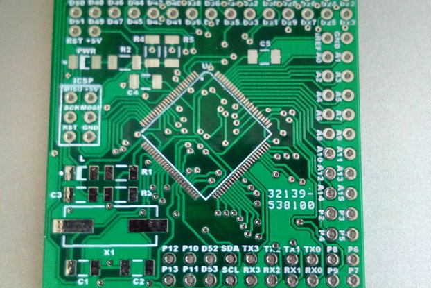
● PCB Materials: You'll need copper-clad board for DIY etching or a professionally fabricated PCB based on your design, along with soldering tools and suitable connectors for creating wiring harnesses.
● Communication Modules: For integration with modern vehicle systems, a CAN bus module (e.g., MCP2515) capable of communication speeds up to 1 Mbps may be required.
Necessary Software Tools
● Open-Source Engine Control Software: Platforms like Speeduino are popular choices, providing readily available firmware specifically designed for Arduino-based ECUs, including code for fuel and ignition mapping.
● PCB Design Software: Free design tools such as KiCad are excellent for creating custom ECU PCB layouts, ensuring correct trace widths (e.g., 0.5mm for signal lines, 2mm for power lines).
● Programming Environment: The Arduino IDE is used for writing code, compiling, and uploading the firmware to your Arduino board.
Step-by-Step Guide to Constructing Your ECU PCB
With your tools and components assembled, let's proceed with the design and construction of your custom DIY ECU PCB. This guide assumes a basic understanding of electronics, including soldering techniques and interpreting circuit schematics.
Defining Project Scope
Begin by clearly outlining the specific functions your ECU will manage. For a foundational hobbyist engine management system, concentrate on fuel injection and ignition timing for a single-cylinder or small engine. Compile a list of all sensors and actuators you intend to use, ensuring your chosen Arduino board has a sufficient number of available pins (e.g., 14 digital I/O pins for a basic setup).
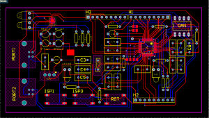
Schematic Design
Utilize your chosen PCB design software to develop a detailed schematic that illustrates the connections between your Arduino and all peripheral components. This should include:
● Analog inputs configured for sensor signals (e.g., 0-5V from a throttle position sensor).
● Digital outputs designed to control injectors and ignition, typically through transistors or MOSFETs.
● Power regulation circuitry to step down the vehicle’s 12V supply to the 5V required by the Arduino (e.g., using an LM7805 regulator rated for 1A).
Ensure meticulous attention to proper grounding techniques to mitigate noise interference, which can otherwise cause sensor reading inaccuracies of up to 0.1V.
PCB Layout Creation
Translate your completed schematic into a physical PCB layout. Critical considerations include keeping high-current traces, such as those for injectors, short and wide (at least 2mm) to safely handle currents ranging from 5-10A. Position sensitive analog components geographically distant from noisy digital signal paths to preserve signal integrity. Aim for a compact board size, perhaps around 100mm x 80mm, to allow for convenient enclosure integration.
Suggested Reading: Optimizing ECU PCB Performance: A Guide to Layer Stackup Design
PCB Fabrication
Once your design is finalized, you have two primary options for fabricating the fast turn PCB: either etch it yourself at home using a copper-clad board and ferric chloride, or opt for professional manufacturing services. For hand-soldering, ensure the board is designed to accommodate through-hole components, which are generally more manageable for hobbyists than surface-mount devices.
Component Assembly and Soldering
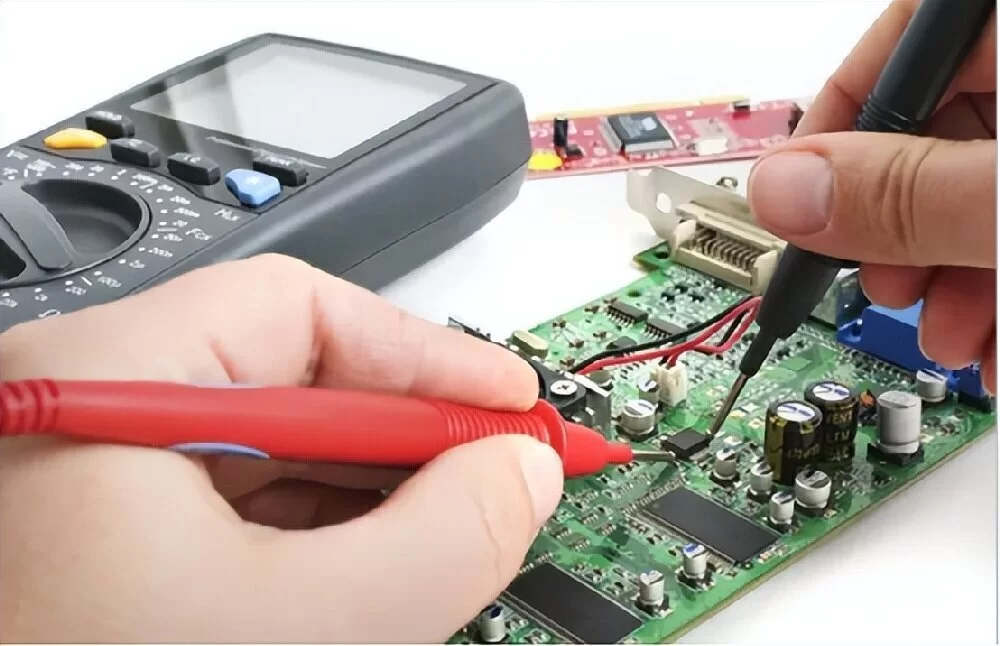
Carefully solder all components onto the PCB. It’s typically best to start with lower-profile components like resistors, then proceed to larger items such as connectors. Always verify the correct polarity for components like capacitors and diodes to prevent damage. Use a multimeter to perform continuity tests, confirming there are no unintended short circuits, particularly on power traces carrying 12V.
Programming the Arduino
Download an appropriate open-source engine control firmware, such as Speeduino, which is compatible with Arduino boards for hobbyist engine management applications. Upload this firmware using the Arduino IDE. Subsequently, configure key settings like injector pulse width (e.g., 2ms at idle) and ignition advance (e.g., 10 degrees before top dead center at 1000 RPM). A tuning interface will be necessary to fine-tune these parameters based on live engine data.
Testing and Troubleshooting
Connect your newly built DIY ECU PCB to either a test engine or a simulated setup. Systematically verify all sensor readings—for example, a MAP sensor should indicate approximately 100 kPa at sea level with the engine off. Confirm that actuators respond as expected, such as hearing an injector click when triggered. Should any issues arise, a logic analyzer can be invaluable for checking signal timing, ensuring that pulses align within 1ms of their expected values.
Common Challenges in Hobbyist Engine Management
While the journey of building a personal ECU PCB is highly gratifying, it is not without its hurdles. Several common challenges frequently arise, and understanding how to address them is key to a successful project.
Managing Signal Noise
Engine environments are inherently noisy, with significant electromagnetic interference that can corrupt sensor signals. To counteract this, employ shielded cables for sensitive connections and incorporate bypass capacitors (e.g., 0.1μF) near sensor inputs to effectively filter out unwanted noise.
Mitigating Heat and Vibration
Engines generate considerable heat, often exceeding 100°C, and significant vibration. It is crucial to house your PCB within a robust, protective enclosure and to select components that are rated for high temperatures, ideally at least 125°C.
Addressing Processing Speed Limitations
A standard Arduino, typically operating at 16 MHz, may struggle to manage the complex real-time calculations required for multi-cylinder engines. For more demanding or advanced projects, consider upgrading to microcontrollers with higher clock speeds, such as those in the STM32 series, which can reach up to 72 MHz.
Safety Measures for DIY ECU Projects
Engaging with engine electronics inherently involves certain risks. Adhering to fundamental safety protocols is paramount to preventing accidents and protecting your equipment.
Always disconnect the vehicle's battery before undertaking any wiring work to eliminate the risk of short circuits, as a 12V system can deliver over 100A in a fault condition.
Before integrating your ECU into a live engine, thoroughly test it on a bench setup or with a simulator. This precaution helps prevent potential damage from incorrect outputs or faulty logic.
Install appropriate fuses (e.g., 5A rating) on all power lines to provide protection against overcurrent situations.
Enhancing Your Arduino ECU's Capabilities
Once your foundational DIY ECU PCB is operational, there are numerous avenues to expand its functionality with additional advanced features.
Integrating Data Logging
Consider adding an SD card module to enable data logging. This allows your ECU to record critical engine data, such as RPM and fuel consumption, at a frequency of about 10 Hz for subsequent analysis and performance review.
Bluetooth Monitoring
Incorporate a Bluetooth module, like the HC-05, to facilitate real-time engine monitoring directly on a smartphone. This can operate effectively at standard baud rates, such as 9600, providing convenient access to live operational data.
Advanced Tuning Features
Utilize open-source tuning software to develop sophisticated custom fuel maps. This enables precise adjustments to injector timing, often in increments as fine as 0.1ms, allowing for meticulous optimization of engine performance.
The Advantages of Open-Source Engine Control Systems
Open-source engine control systems have fundamentally transformed the landscape for hobbyists. They offer free access to firmware and tuning tools developed and supported by a global community, effectively eliminating the need for expensive proprietary systems that can cost well over $1000. Platforms like Speeduino benefit from continuous updates and robust support from a worldwide network of DIY enthusiasts, ensuring that your Arduino-based ECU remains current, adaptable, and highly functional.
Begin Your DIY ECU PCB Project Today
Constructing your own ECU PCB provides an exceptional entry point into the world of hobbyist engine management. By combining an Arduino microcontroller, open-source engine control software, and a custom-designed HDI PCB, you can create a highly personalized solution perfectly tailored for your engine project. Each stage of the process—from circuit design to programming and rigorous testing—imparts invaluable knowledge in both electronics and automotive systems.
With this guide as your foundation, you are now well-prepared to commence your DIY ECU PCB project. Proceed methodically, conduct thorough testing at each step, and savor the experience of transforming your engine control concepts into a functional reality. Whether your application is a go-kart, a motorcycle, or a vintage automobile, your custom-built ECU will grant you comprehensive control over its performance and fuel efficiency.


