Why Develop an ATM Interface Using Arduino?
Constructing an ATM interface with Arduino offers an engaging project that seamlessly blends hardware and software development skills. This endeavor simulates real-world banking transactions, serving as an excellent educational tool for understanding user interfaces, managing input, and processing data. By designing a custom printed circuit board (PCB) for this project, you can achieve a compact, professional-grade setup precisely tailored to your specifications. This tutorial is designed to guide you through the process, covering everything from component selection to step-by-step assembly and coding, ensuring you can confidently replicate this project.
What Materials Are Needed for Your Arduino ATM Project?
Before you begin the construction process, it's essential to gather all the necessary components and tools. Having everything prepared beforehand will ensure a smoother and more efficient build.
Essential Components Checklist
● Arduino Board: A microcontroller, such as an Arduino Uno or Nano, will serve as the central processing unit for your ATM interface.
● Keypad: A 4x4 matrix keypad is required for user input, including PIN entry and menu selections.
● LCD Display: A 16x2 Liquid Crystal Display equipped with an I2C module will show menus and transaction details.
● Buzzer: A small buzzer is useful for providing auditory feedback, such as transaction confirmations or error alerts.
● Resistors and Capacitors: Various values are needed for circuit stability (e.g., 220-ohm resistors for LEDs or keypad pull-downs; 0.1μF decoupling capacitors).
● LEDs: Light-Emitting Diodes can indicate status (e.g., green for success, red for error).
● Prototyping Tools: A breadboard and jumper wires are essential for initially prototyping the circuit.
● Custom PCB: A specially designed and manufactured PCB will neatly house all your components.
● Software: The Arduino IDE is necessary for writing and uploading the program to your Arduino board.
● Soldering Equipment: A soldering iron, solder, and flux are required for assembling the PCB components.
Understanding and Designing the ATM Interface Circuit
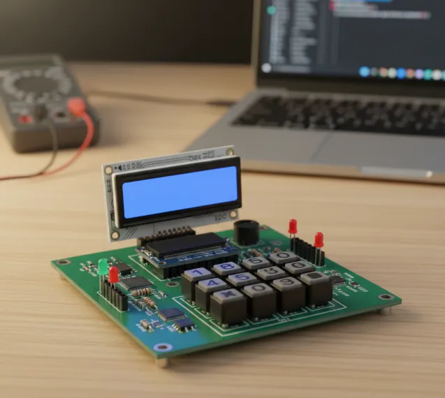
The ATM interface project aims to replicate fundamental ATM functions like PIN entry, transaction selection (withdrawal, balance check, deposit), and displaying outcomes. Your Arduino will interpret keypad inputs, show information on the LCD, and simulate transactions by managing a virtual balance in its memory. While simplified, this setup mirrors core ATM operations, providing a robust learning foundation.
The Role of a Custom PCB
A fast turn custom PCB is crucial because it transforms a cluttered breadboard setup into a streamlined, permanent solution. It enhances signal integrity, significantly reduces electrical noise, and boosts the project's overall durability. For example, a well-engineered PCB can manage impedance matching for faster signal speeds, typically targeting a 50-ohm impedance for digital signals in microcontroller applications.
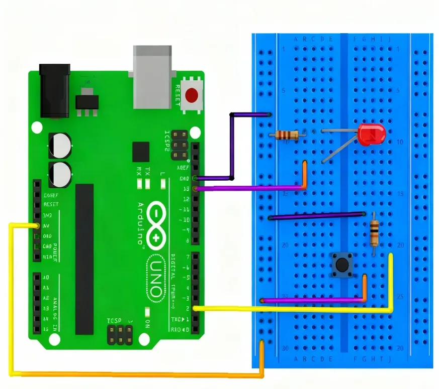
Circuit Design and Prototyping
Begin by prototyping the circuit on a breadboard to thoroughly test all connections before proceeding to PCB design.
● Keypad to Arduino: Connect the 4x4 keypad to your Arduino's digital pins (e.g., D2 to D9 on an Arduino Uno). The keypad uses a matrix scanning method to register key presses.
● LCD Display to Arduino: Utilize an I2C module with the LCD to conserve Arduino pins. Connect SDA to A4 and SCL to A5 (for Uno), ensuring proper power (5V) and ground connections.
● Buzzer and LEDs: Connect the buzzer to a digital pin (e.g., D10) via a 220-ohm resistor. Status LEDs can be connected to other digital pins (e.g., D11 and D12) with similar resistors.
Once the breadboard prototype functions correctly, meticulously document the connections to prepare for the PCB design phase. Ensure ample spacing for components and consider adding decoupling capacitors (e.g., 0.1μF) near the Arduino's power pins to filter out noise.
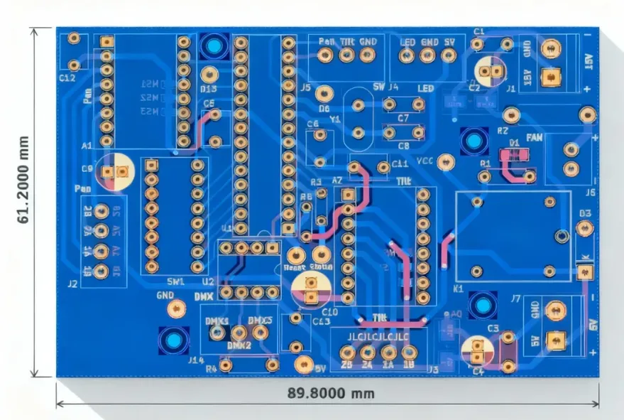
Crafting Your Custom PCB for the ATM Interface
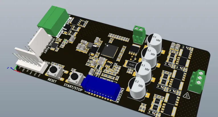
Designing a custom PCB elevates your Arduino ATM project to a professional standard. A custom board ensures a compact arrangement, minimizes wiring errors, and significantly enhances reliability.
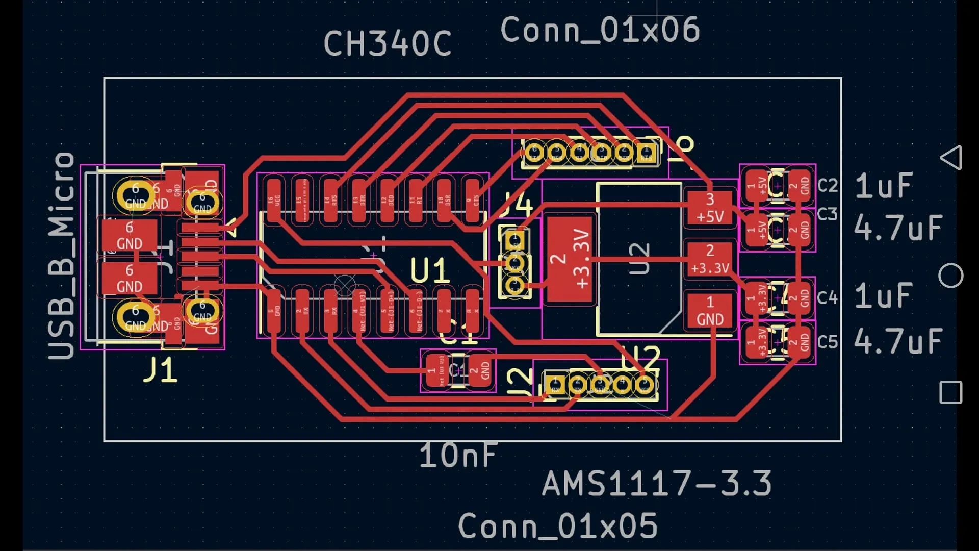
PCB Design Workflow
● Software Selection: Choose a suitable PCB design software. Many free or open-source tools with active community support are available for beginners.
● Schematic Capture: Translate your breadboard prototype into a formal schematic diagram. Include all components (Arduino, keypad, LCD, etc.) and clearly label all connections.
● Board Layout: Arrange components logically on the PCB. Position the Arduino near the center for convenient access to its pins. Route traces with a minimum width of 0.25mm for low-current signals and incorporate robust ground planes to minimize noise.
● Mounting Holes: Add designated holes for screws to securely fasten the PCB within an enclosure.
● Manufacturing Preparation: Once your design is finalized, export the Gerber files. These files are then sent to a trusted PCB fabrication service for high-quality production.
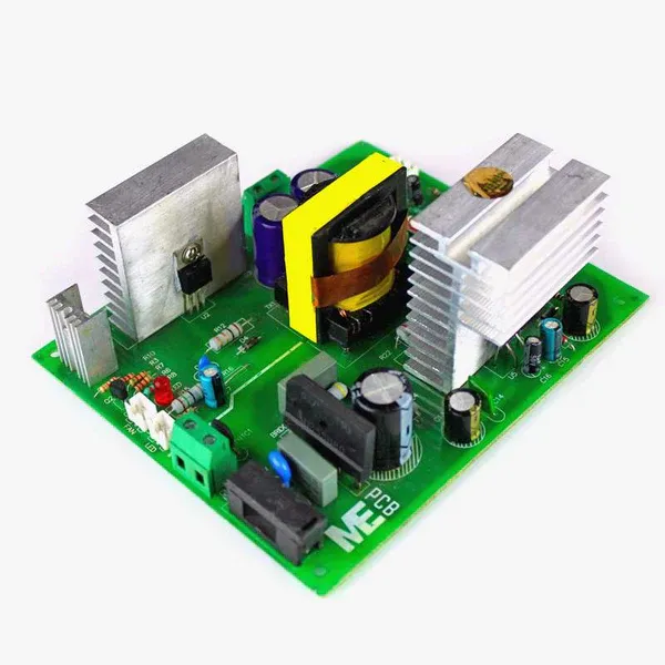
Custom PCB design also facilitates superior thermal management. For an ATM interface that operates for extended periods, strategically placed copper pours on the HDI PCB can effectively dissipate heat, maintaining a stable operating temperature, typically between 25-30°C under normal conditions.
Programming the Arduino for ATM Functionality
With the hardware components ready, the next step is to program the Arduino to manage the ATM’s operations. You will need to install specific libraries, such as "Keypad" and "LiquidCrystal_I2C," within the Arduino IDE to control the keypad and LCD display, respectively.
Core Code Structure and Logic
● Component Initialization: In the setup() function, configure the keypad, LCD, and all other necessary pins.
● PIN Entry: The system will prompt the user to input a 4-digit PIN using the keypad. This input is then compared against a predefined correct PIN (e.g., "1234"). If the PIN is correct, the system proceeds to the main menu; otherwise, an error message is displayed, and the buzzer sounds.
● Transaction Menu: The LCD will present options such as "1. Check Balance," "2. Withdraw," and "3. Deposit." User selection is made via the keypad.
● Transaction Simulation: For withdrawals, the system verifies if the requested amount is available in the virtual balance (starting with an initial balance of, say, 1000 units). The balance is updated accordingly, and the transaction result is displayed on the LCD.
This code structure ensures secure access and provides essential user feedback, closely mimicking a real ATM interaction. Adjust timing delays, such as a 200ms tone for the buzzer, to optimize user experience.
Conclusion: Take Your Arduino ATM Project Further
Building an ATM interface with Arduino and a custom PCB is an exciting and educational project that enhances your skills in electronics, programming, and circuit design. From wiring the keypad to displaying simulated transactions on an LCD screen, this guide has walked you through each essential step to ensure success. By incorporating a custom PCB, your project becomes more durable, reliable, and visually professional.
Whether it’s for a school project or personal innovation, the possibilities are limitless. You can extend the system with advanced features such as RFID card authentication or database integration for real transaction tracking. Start creating today, and bring your ideas to life with AIVON—your trusted partner for high-quality PCB manufacturing and prototyping solutions.