Why is a Security Camera PCB Schematic Essential for Design and Repair?
For anyone delving into the realm of security camera design or repair, comprehending a security camera PCB schematic is an absolutely vital initial step. A PCB (Printed Circuit Board) schematic functions as the fundamental blueprint, meticulously detailing the electrical interconnections among components within a CCTV camera. This comprehensive tutorial will systematically break down the core principles of interpreting security camera PCB layouts, elucidate complex CCTV circuit diagrams, and guide you through understanding the specific camera PCB components. Whether your interest lies in DIY electronics or in mastering sophisticated security camera schematics, this step-by-step guide will facilitate your navigation through the process.
Navigating the Blueprint
We will thoroughly explore everything from the foundational concepts to practical techniques for interpreting and effectively utilizing these intricate designs. By the culmination of this guide, you will possess a robust understanding of how these circuits operate and how to proficiently apply this knowledge in practical, real-world applications.
What Constitutes a Security Camera PCB Schematic?
A security camera PCB schematic is a highly detailed diagram that graphically represents the electrical connections between individual components mounted on a printed circuit board specifically designed for surveillance cameras. It serves as an indispensable roadmap for both engineers and hobbyists, providing clarity on how electrical power, digital signals, and data streams flow within the device. Such schematics are fundamentally critical for the successful design, meticulous troubleshooting, or precise repair of any CCTV system.
The Circuit's Inner Workings
In essence, the schematic reveals the precise location and connectivity of every part—including the image sensor, power regulation circuitry, or video output chip—within the overall circuit. It also highlights crucial connections, such as how a 12V power input is meticulously stepped down to 3.3V for specific, sensitive components. Whether your objective is constructing a DIY electronics security camera or performing an in-depth analysis of an existing design, a profound mastery of these diagrams is paramount to your success.
Why is Understanding CCTV Circuit Diagrams So Important?
Proficiency in reading CCTV circuit diagrams provides invaluable insight into the core operational mechanics of a security camera. By developing the ability to interpret these layouts, you can accurately diagnose common issues such as a faulty power supply (a frequent cause of cameras failing to power on) or a compromised image sensor (leading directly to subpar video quality). This specialized knowledge is indispensable for several key applications:
● Custom System Design: Crafting bespoke security camera systems tailored to specific requirements.
● Malfunction Diagnostics: Repairing inoperative devices by systematically tracing the signal pathways.
● System Enhancements: Improving existing setups through modifications, such as integrating advanced night vision capabilities.
For enthusiasts of DIY electronics, a solid grasp of camera PCB components furthermore unlocks numerous opportunities for innovative projects, including the seamless integration of surveillance cameras with smart home automation platforms.
What Are the Key Components of a Security Camera PCB?
Before delving into the intricacies of interpreting security camera PCB layouts, let’s systematically break down the fundamental components typically found on such a board. Each element fulfills a distinct and crucial role in the processes of capturing, processing, and transmitting video footage.
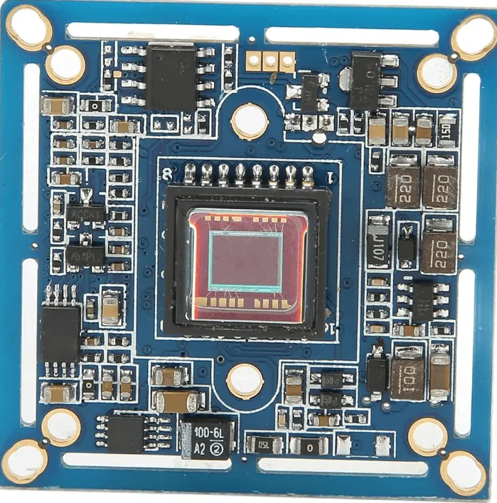
1. The Image Sensor
The image sensor, frequently a CMOS or CCD chip, serves as the central processing unit of the camera. Its primary function is to convert incoming light into corresponding electrical signals, thereby generating video or still images. For instance, a common CMOS sensor might operate at 3.3V and be capable of outputting data at a rate of 30 frames per second for full 1080p resolution.
2. Power Management Circuitry
This dedicated section is responsible for regulating the incoming supply voltage (typically 12V DC for the majority of CCTV cameras) and stepping it down to lower, stable voltages such as 5V or 3.3V for the various integrated circuits. A typical power management IC might be designed to handle current loads of up to 1A, ensuring stable and reliable operation across the board.
3. Microcontroller Unit (MCU)
The Microcontroller Unit (MCU) is tasked with processing the raw signals received from the image sensor and managing a range of sophisticated camera functionalities, including motion detection algorithms and video compression. In contemporary cameras, the MCU frequently operates at clock speeds of 100 MHz or higher to ensure highly efficient data processing.
4. Video Output Module
This component's role is to convert the processed video data into a format suitable for transmission, which can be either analog (e.g., CVBS) or digital (e.g., IP over Ethernet). For analog outputs, precise impedance matching at 75 ohms is absolutely critical to prevent significant signal loss and ensure video quality.
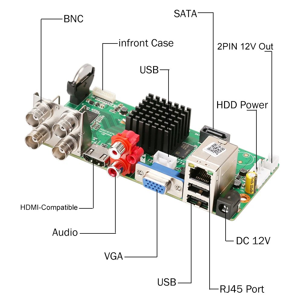
5. Connectors and Ports
These essential interfaces include power input jacks, various video output ports, and, in the case of IP cameras, often network (RJ45) connectors. A meticulously optimized layout for these connectors is paramount to minimize signal interference, particularly for high-speed data transmission lines.
Suggested Reading: Soldering and Assembling Security Camera PCBs: A Practical DIY Guide
A Step-by-Step Guide to Interpreting Security Camera PCB Schematics
Now equipped with a foundational understanding of the key components, let’s proceed with a systematic, step-by-step approach to reading and interpreting a security camera HDI PCB schematic. This guide is specifically tailored for both novice and intermediate enthusiasts engaged in DIY electronics security camera schematics.
Step 1: Pinpoint the Power Supply Section
Begin by locating the primary power input on the schematic, which is typically denoted by a symbol for a DC voltage source or explicitly labeled as “VIN.” Systematically trace the conductive paths to observe how the input voltage is distributed across the board. Look for critical components such as voltage regulators (e.g., a 7805 integrated circuit for a 5V output) or various capacitors (often 10μF or 100μF) that are crucial for stabilizing the power supply. A thorough understanding of this section is vital for ensuring the camera receives the correct, stable voltage, free from damaging spikes.
Step 2: Locate the Image Sensor and Its Signal Path
Identify the image sensor on the schematic, which is usually represented by a distinct rectangular block featuring pins designated for power, ground, and data output. Carefully follow the data lines to observe their connections to the Microcontroller Unit (MCU) or the dedicated video processor. Signal pathways frequently incorporate resistors or filters specifically designed to reduce electronic noise, thereby ensuring a clear video output, even at speeds like 27 MHz for standard HD signals.
Step 3: Examine the Video Output Circuitry
Trace the signal path from the video processor to the final video output port. For traditional analog cameras, you will typically find a 75-ohm resistor strategically placed near the output to ensure precise impedance matching with coaxial cables. For advanced IP cameras, look for specific Ethernet transformers or RJ45 connectors. This step is indispensable for comprehending how processed video data is externally transmitted from the camera.
Step 4: Investigate Supporting Circuits
Identify any supplementary circuits that enable additional functionalities, such as infrared (IR) LEDs for night vision, which are commonly controlled by discrete transistors or dedicated integrated circuits. These auxiliary circuits might activate based on input from a light sensor, potentially drawing approximately 200mA per LED array. Recognizing these extra features helps in understanding the camera's full operational capabilities.
Step 5: Review Grounding and Noise Suppression Techniques
Pay close attention to the layout of ground planes (typically marked as “GND”) and the placement of decoupling capacitors strategically located near integrated circuits. These elements are crucial for preventing interference in high-frequency circuits, thereby ensuring stable and reliable operation. Inadequate grounding can lead to discernible video artifacts or flickering, making this a critical aspect of any robust circuit design.
What Are Common Challenges in Understanding Camera PCB Components?
Interpreting security camera PCB layouts can present difficulties, particularly for newcomers. Here are some prevalent obstacles and effective strategies to surmount them.
1. Overly Complex Diagrams
Some schematics feature dozens of components and intricate interconnections, making them challenging to follow. To manage this complexity, systematically break down the schematic into smaller, more manageable sections, beginning with the power supply and then progressing to signal flow. Utilizing a highlighter or a digital annotation tool to trace individual pathways one at a time can greatly enhance clarity.
2. Unfamiliar Circuit Symbols
You may encounter circuit symbols for various diodes, transistors, or integrated circuits that are new to you. Always keep a comprehensive reference chart readily accessible or leverage online resources to quickly decipher these symbols. The majority of professional schematics also include a legend or a detailed component list.
3. Incomplete Specifications
Not all schematics explicitly provide critical details such as precise voltage ratings or specific resistor values (e.g., 1kΩ). In such instances, cross-reference the components with their respective datasheets or, if a physical board is available, directly measure their values using a multimeter.
Tips for Designing Your Own Security Camera PCB Schematic
If you are embarking on the exciting challenge of designing DIY electronics security camera schematics from the ground up, here are practical tips to guide your initial efforts.
1. Begin with a Block Diagram
Before attempting to draw a full, intricate schematic, first sketch a simplified block diagram that outlines the major functional sections: power management, image sensor, processor, and video output. This preparatory step simplifies the subsequent design process and ensures that no critical elements are overlooked.
2. Utilize Industry-Standard Design Software
Leverage professional PCB design software tools to create highly accurate and precise schematics. These advanced tools typically include extensive libraries of pre-built component models specifically for security cameras, which significantly saves design time and minimizes potential errors.
3. Optimize for Signal Integrity
Strategically place high-speed components, such as the image sensor, in close proximity to the main processor to minimize undesirable signal propagation delays. Furthermore, design power lines to be both short and sufficiently wide to efficiently handle currents, potentially up to 2A, without experiencing significant voltage drops.
4. Implement Incremental Testing
Build and rigorously test smaller, individual sections of your circuit before attempting to assemble the complete fast turn PCB. For instance, verify that the power circuit consistently outputs a stable 3.3V before connecting and powering the sensitive image sensor.
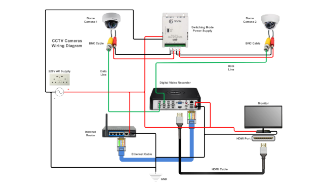
Practical Applications of CCTV Circuit Diagrams in Real-World Scenarios
A deep understanding of CCTV circuit diagrams is not merely an academic exercise—it possesses significant real-world utility. For example, professional technicians frequently consult schematics to diagnose why a camera might not be recording, often pinpointing issues such as a blown fuse within the power supply line. Hobbyists, on the other hand, might use a schematic as a guide to modify a camera to support higher resolutions by upgrading the image sensor, ensuring compatibility with the existing circuit architecture.
In professional environments, engineers depend heavily on these diagrams to design robust surveillance systems tailored for specific operating conditions, such as outdoor cameras incorporating advanced weatherproofing circuits that draw minimal power (e.g., under 5W) to maximize energy efficiency. Regardless of your specific objective, a solid grasp of schematics empowers you to innovate, troubleshoot, and solve complex problems effectively.
How to Troubleshoot Using Security Camera PCB Schematics
When a security camera malfunctions, its schematic becomes your most invaluable tool for effective troubleshooting. Here’s a concise guide to using it:
● No Power: Systematically check the power input section and the voltage regulator circuitry for any anomalies. Use a multimeter to measure voltages at critical points to confirm they match the expected 12V or 5V.
● Poor Video Quality: Carefully inspect the image sensor and its entire signal path for any loose connections or visibly damaged components. Also, examine any noise filters or capacitors in the path that might be faulty.
● No Output Signal: Trace the video output circuit from the processor to ensure the signal successfully reaches the connector. Test the impedance at the output port to identify any potential mismatches.
By utilizing a multimeter in conjunction with the schematic, you can precisely verify voltages and continuity, thereby accurately pinpointing the exact location of any failures.
Where Can You Find Resources for Learning More About Security Camera PCB Layouts?
If you are eager to further enhance your expertise in interpreting security camera PCB layouts, consider exploring these valuable resources:
● Online Tutorials and Forums: Engage with specialized online communities and tutorials dedicated to electronics and CCTV systems.
● Component Datasheets: Study the datasheets for common camera components, such as CMOS sensors or video encoder integrated circuits.
● Specialized Courses: Enroll in free or paid courses focusing on circuit design specifically tailored for surveillance technology.
Moreover, consistent hands-on practice with actual circuit boards and their corresponding schematics will significantly accelerate your learning curve. Begin with simpler analog cameras before progressing to the complexities of modern IP systems.
Conclusion: Mastering the Art of Security Camera PCB Schematics
A comprehensive understanding of security camera PCB schematics represents a powerful and indispensable skill for anyone deeply involved in surveillance technology or DIY electronics. From meticulously identifying crucial components like the image sensor to precisely tracing intricate signal paths and efficiently troubleshooting various issues, this step-by-step tutorial has meticulously covered all the essential aspects of reading and designing CCTV circuit diagrams. With dedicated practice, you will steadily gain confidence in interpreting even the most complex layouts and proficiently applying your acquired knowledge to real-world projects.
Whether you are a hobbyist constructing a custom camera or a seasoned professional optimizing an elaborate security system, the ability to accurately decode and create schematics will distinctly elevate your capabilities. Continue to explore, test, and learn persistently to remain at the forefront of this constantly evolving technological field. For unparalleled quality in PCB manufacturing and expert design support, entrust your security camera projects to our specialized expertise.