Why is Thoughtful PCB Design Essential for Drone Flight Controllers?
The flight controller acts as the central intelligence of any drone, orchestrating everything from motor commands to the intricate processing of sensor data. Consequently, the design of its printed circuit board (PCB) is a critical factor influencing overall drone performance. A poorly conceived PCB can introduce significant problems, such as electrical interference, damaging overheating, or even catastrophic system failures mid-flight.
Conversely, a meticulously optimized drone flight controller PCB layout guarantees smooth operations, minimizes electrical noise, and ensures long-term dependability. This guide delves into the crucial aspects of designing such PCBs, offering actionable advice to help engineers, hobbyists, and industry professionals achieve superior results. By carefully planning and executing each design phase, you can build a flight controller that ensures stable flight, efficient power usage, and resilience under challenging conditions.
What Are the Core Principles for an Effective PCB Layout?
The physical arrangement of components and traces on a drone flight controller PCB profoundly impacts its operational characteristics. A well-executed layout is fundamental for mitigating interference, ensuring efficient power delivery, and maintaining a compact form factor. Adhering to specific guidelines during the design phase establishes a robust foundation for the entire system.
Strategic Component Placement
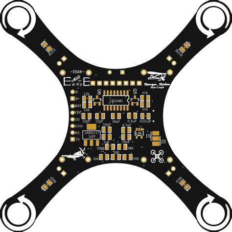
Critical components, including the microcontroller, gyroscopes, and accelerometers, should be positioned centrally on the board. This placement helps to lessen the impact of vibrations during flight. High-speed signal components require close proximity to each other to minimize trace lengths, which in turn reduces signal propagation delays and preserves data accuracy. For example, traces connecting the Inertial Measurement Unit (IMU) to the processor are ideally kept under 10 mm.
Optimized Layer Stackup and Grounding
Whenever feasible, a 4 layer PCB board stackup is highly recommended. This configuration permits dedicated layers for power, ground, and signal routing, significantly enhancing electrical isolation and reducing noise. A typical arrangement might feature a top signal layer, followed by a solid ground plane, then a power plane, and finally a bottom signal layer. Employing a continuous ground plane beneath high-frequency components is crucial; it establishes a stable reference for signals and can diminish electromagnetic interference (EMI) by up to 30%.
Precise Trace Routing Techniques
High-speed traces, such as those used for SPI or I2C communication, must be kept short and routed directly. It is vital to avoid routing traces over split ground planes, as this can introduce undesirable noise and signal integrity issues. For critical high-speed signals, aiming for a trace impedance of approximately 50 ohms helps to match component requirements and prevent reflections, ensuring cleaner data transmission.
How Can Signal Integrity Be Maintained in Drone PCBs?
Reliable signal integrity within a drone’s PCB is paramount for accurate data exchange between vital components like sensors, processors, and Electronic Speed Controllers (ESCs). Compromised signal integrity can lead to data corruption, delayed responses, or unpredictable drone behavior. Several techniques can be employed to optimize this crucial aspect of the design.
Minimizing Crosstalk and Managing Impedance
To prevent crosstalk, which is unwanted coupling between adjacent signal traces, it is advisable to separate high-speed digital signals from analog signals by a distance of at least three times the trace width. For instance, if a trace width is 0.2 mm, a minimum separation of 0.6 mm should be maintained. Furthermore, matching the impedance of traces to the components they connect is essential. For high-speed lines such as USB or UART, maintaining a 50-ohm impedance prevents signal reflections that can degrade data quality. Utilizing PCB design software with built-in impedance calculators can facilitate precise routing.
Strategic Decoupling and Trace Length Control
Decoupling capacitors play a vital role in filtering out power supply noise. They should be placed as close as possible to the power pins of integrated circuits (ICs). A common practice is to use a 0.1 µF capacitor near each power pin to effectively stabilize the voltage supply and mitigate spikes. Additionally, avoiding excessively long traces is crucial, particularly for high-frequency signals. Long traces can act as antennas, making the board susceptible to picking up external noise. Keeping critical signal traces under 25 mm, especially for frequencies above 100 MHz, is an excellent rule of thumb to preserve signal fidelity.
What Are Best Practices for Thermal Management in Drone PCBs?
Drones frequently operate in challenging environments, where components like processors and power regulators generate considerable heat. Effective thermal management for the drone’s PCB is therefore indispensable to prevent overheating, which can lead to premature component failure or a shortened operational lifespan.
Heat Dissipation Techniques
Incorporating thermal vias underneath high-heat-generating components, such as voltage regulators, is an effective strategy. These vias transfer heat efficiently to a lower layer or a dedicated heat sink. For a component dissipating 2W of heat, it's recommended to include at least 4-6 thermal vias, each with a diameter of 0.3 mm. Expanding the copper area around heat-generating components through copper pours can also significantly enhance heat spreading. A copper pour of 2 oz/ft² offers superior heat dissipation compared to a standard 1 oz/ft² layer.
Component Spacing and Material Choices
Preventing heat concentration requires thoughtful component spacing. Avoid grouping all heat-intensive components together; instead, distribute them across the board to facilitate better airflow and heat distribution. While material selection will be discussed in more detail, it’s crucial to consider PCB substrates with good thermal conductivity during the initial design phase. Proper thermal management ensures the drone’s flight controller remains reliable, even during extended missions or when operating in warmer climates.
How Should Materials Be Selected for Drone PCB Construction?
The choice of materials for a drone’s PCB significantly influences its overall performance, durability, and critical weight. Opting for the right materials ensures the board can effectively handle high frequencies, dissipate heat efficiently, and withstand the mechanical stresses inherent in flight.
Substrate Options for Diverse Needs
PCB FR4 material remains the most common PCB substrate, prized for its affordability and respectable electrical properties. It performs well in many standard drone applications, offering a dielectric constant of approximately 4.5 and thermal resistance up to 130°C. For drones demanding high-speed data transmission, consider laminates engineered for high frequencies. These materials typically feature lower dielectric constants (around 3.0-3.5) to minimize signal loss, making them ideal for sensitive circuits like GPS or video transmission. For extreme temperature operation or flexible designs, polyimide offers exceptional thermal stability (up to 260°C) and can be used to create compact, flexible PCBs.
Copper Weight Considerations
The weight of the copper traces also plays a crucial role. For most drone PCBs, a copper weight of 1-2 oz/ft² is generally appropriate. While thicker copper improves current-carrying capacity and enhances heat dissipation, it also adds to the overall weight of the board. Therefore, designers must carefully balance these factors to meet the drone’s specific performance and flight time requirements.
Strategies for Optimizing Drone PCB Weight and Durability
Weight is a paramount consideration in drone design, directly impacting flight duration and maneuverability. Achieving an optimized drone PCB weight without compromising performance demands strategic design choices. Beyond weight, ensuring the PCB’s durability is vital for long-term reliability in demanding flight conditions.
Minimizing Physical Dimensions and Material Use
To reduce weight, design the most compact PCB possible, utilizing vertical component stacking where appropriate. A smaller board naturally requires less material. For example, a 30x30 mm board is common for many micro-drones and is inherently lighter than larger alternatives. Employing thinner PCB substrates (e.g., 0.8 mm instead of 1.6 mm) can further trim weight, provided the thinner material still meets necessary structural and thermal requirements. Additionally, implementing selective copper thickness—using lighter copper (1 oz/ft²) for low-current areas and reserving thicker copper (2 oz/ft²) only for high-current paths like power lines to ESCs—helps to optimize weight distribution.
Enhancing Robustness and Reliability
Removing unnecessary PCB material by adding cutouts or slots in areas devoid of components or traces can reduce weight by 10-15% without affecting functionality. For increased durability, a robust power distribution network is essential to manage high currents (often 20-50A for quadcopters), requiring wide traces (at least 2 mm for high-current paths) and multiple vias to minimize resistance. Incorporating EMI shielding for sensitive components like GPS modules, perhaps through a small metal enclosure or a grounded copper pour, helps block external interference. Finally, applying a conformal coating provides crucial protection against moisture, dust, and vibration damage, particularly for drones operating in harsh environments.
Conclusion: Crafting the Ideal Drone Flight Controller PCB
Designing a drone flight controller PCB is an intricate yet profoundly rewarding endeavor. By meticulously focusing on a well-conceived drone flight controller PCB layout, rigorously ensuring drone PCB signal integrity, expertly managing drone PCB thermal performance, judiciously selecting the most suitable materials, and strategically optimizing drone PCB weight, you are poised to engineer a board that delivers unparalleled performance and unwavering reliability.
Every minute detail holds significance, from the precise placement of individual components to the informed choice of the substrate material. Armed with the practical insights and strategic approaches detailed in this guide, you are exceptionally well-equipped to navigate and overcome the complexities of modern drone PCB design. Begin integrating these best practices into your forthcoming projects, and witness your drone's operational capabilities ascend to remarkable new altitudes.
AIVON, a well-known online PCB manufacturer, is dedicated to empowering your journey with high-quality PCB manufacturing solutions, specifically tailored to meet the evolving and unique demands of drone technology. Together, let’s innovate and construct the future of flight.


