What Role Do Avionics PCBs Play in Model Rocketry?
Avionics Printed Circuit Boards (PCBs) function as the intelligent core of a model rocket, orchestrating critical operations such as tracking altitude, initiating parachute deployment, logging flight data, and in some advanced systems, contributing to flight stabilization. For electronics enthusiasts engaged in rocketry, crafting a bespoke avionics PCB offers the unique opportunity to fine-tune the system to their rocket's specific needs, transforming it into a deeply rewarding DIY endeavor.
This guide is specifically tailored to demystify the creation of a straightforward avionics circuit, making it accessible even for novices. The emphasis is on incorporating only essential components and employing direct design principles, all while ensuring robust reliability crucial for enduring the rigorous demands of a rocket launch. By the conclusion of this discussion, you will possess a clear, actionable framework for constructing a fundamental PCB design that perfectly aligns with your rocketry aspirations.
Why Should You Consider a Custom Avionics PCB for Your Rocket Project?
While a variety of commercial flight computers are readily available, opting to design your own model rocketry avionics PCB offers distinct advantages. Firstly, for hobbyists who frequently engage in rocket construction, a custom design proves to be a more economical long-term solution. Secondly, it grants unparalleled control over the features integrated into your system, allowing for the inclusion of specialized sensors or communication modules precisely tailored to your project. Furthermore, it serves as an exceptional educational journey for anyone keen on delving deeper into electronics and hands-on rocketry PCB endeavors.
A custom PCB also champions compactness, a critical factor given the confined spaces within model rockets, which often necessitate electronics to fit within tubes as narrow as 1.5 inches (38 mm) in diameter. Designing your own board ensures that your avionics system is both lightweight and space-efficient, frequently weighing less than 50 grams for smaller rockets, thereby optimizing performance without compromising on functionality.
What Are the Core Components of a Basic Rocket Avionics Circuit?
Before delving into the intricacies of design, it's crucial to grasp the fundamental components that constitute a simple avionics HDI PCB for model rocketry. A clear understanding of these elements is key to engineering a system that is both functional and dependable throughout its operational lifespan.
Processing and Sensory Elements
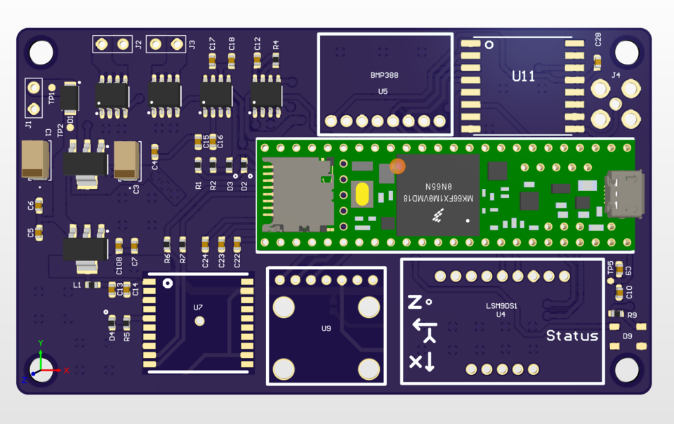
At the heart of your avionics system resides the microcontroller, such as an Arduino-compatible chip like the ATmega328P, which is responsible for processing data and managing various functions. Typically operating at 8-16 MHz, it offers ample power for standard rocketry tasks. An altimeter sensor, commonly a BMP280, measures altitude using barometric pressure, capable of detecting changes as subtle as 1 meter—ideal for precisely timed parachute deployments. Additionally, a 3-axis accelerometer, like the MPU-6050 with a ±16g range, tracks acceleration and orientation, crucial for identifying launch events and apogee.
Power, Deployment, and Data Logging
For stable power delivery, a compact lithium battery (e.g., 3.7V, 500mAh) or a 9V battery paired with a voltage regulator typically supplies 3.3V or 5V to the components. The ignition circuit, vital for parachute deployment or other event triggers, employs a MOSFET or relay to manage currents up to 1-2A for igniting pyrotechnic charges. Finally, a microSD card module enables the logging of critical flight data, such as altitude and speed, providing invaluable information for post-flight analysis and evaluation.
How Do You Design a Basic PCB for Your Model Rocket?
With an understanding of the necessary components, let's navigate the process of designing a straightforward avionics PCB for your model rocket. This section is crafted specifically for beginners and electronics hobbyists in rocketry who are new to the realm of PCB design.
Defining Requirements and Selecting Software
Begin by clearly outlining the essential functions your avionics PCB needs to perform. For a foundational design, concentrate on core tasks such as altitude measurement and parachute deployment, avoiding the temptation to overcomplicate your initial project with advanced features like GPS or real-time telemetry. Subsequently, choose appropriate PCB design software. For novices, user-friendly, free tools with strong community support are ideal, enabling you to create schematics, arrange components, and generate manufacturing files. Crucially, ensure the software supports exporting Gerber files, the industry standard for PCB fabrication.
Schematic Creation and Layout Principles
Proceed to sketch your schematic, which serves as the electrical blueprint for component interconnections. Position your microcontroller centrally, then link it to sensors, the power supply, and output circuits, consistently using a 3.3V or 5V logic level for compatibility. For instance, connect the altimeter to the microcontroller’s I2C pins, incorporating a 4.7kΩ pull-up resistor for signal stability. Once the schematic is finalized, move to the PCB layout phase. Aim for a compact board, ideally under 1.5 x 1.5 inches (38 x 38 mm), to fit within a standard rocket tube. Strategically group related components to minimize trace lengths and electrical noise.
Routing, Mounting, and Verification
For traces, use a minimum width of 0.01 inches (0.254 mm) for low-current signals and wider traces (0.03 inches or 0.762 mm) for power lines to safely handle up to 1A. Incorporate a ground plane on one layer to effectively reduce electrical interference, especially important during high-vibration launches. Add mounting holes, typically 0.1-inch (2.54 mm) diameter, to secure the PCB, and include clearly labeled connectors or solder pads for external elements like batteries and igniters. Before finalizing, rigorously run Design Rule Checks (DRC) using your software to identify and rectify any errors. Finally, export your design as Gerber files, review them with a Gerber viewer, and submit them to a reliable PCB manufacturing service like AIVON for production.
Essential Tips for Testing and Integrating Your Avionics PCB
Once your fast turn custom PCB arrives, the next phase involves assembling, rigorous testing, and seamless integration into your rocket. Following these detailed steps will help ensure a robust and successful deployment.
Assembly and Initial Power-Up Checks
Begin by carefully soldering the components onto your new PCB. Utilize a fine-tip soldering iron (25-30W) and lead-free solder, starting with the smallest parts such as resistors and capacitors before advancing to larger elements like the microcontroller. After assembly, perform an initial power-on test. Connect the battery and verify that the microcontroller successfully boots up. If your design includes serial communication, use a serial monitor to check sensor readings; for example, the altimeter should register a value near zero at ground level.
Bench Testing and Rocket Integration
Proceed to comprehensive bench testing where you simulate various flight conditions. Tilt the board to test the accelerometer's response, and gently blow air over the altimeter to mimic changes in altitude during ascent. Crucially, confirm that the ignition circuit triggers precisely as expected under these simulated conditions. For integration, securely mount the PCB within the rocket's avionics bay, using either screws or a suitable adhesive. Route all connecting wires meticulously to prevent tangling or dislodging due to the intense vibrations experienced during launch, which can generate forces ranging from 10-20g.
Overcoming Common Challenges in DIY Rocketry PCB Design
Embarking on the design of a model rocketry avionics PCB as a beginner can present various obstacles. Being aware of these common issues and understanding their solutions is key to a smoother design and development process.
Mitigating Environmental and Electrical Issues
Rocket launches subject electronics to severe vibrations; therefore, it's crucial to use small, surface-mount components and ensure the PCB is tightly secured within the rocket to prevent any loosening or damage. Power failures can occur if your battery isn't adequately sized for peak current demands, particularly during ignition (which might draw up to 500mA). Adding a capacitor (10-100μF) near the microcontroller can help stabilize voltage fluctuations. Furthermore, high-speed signals are susceptible to noise interference; to counter this, keep traces as short as possible (under 2 inches or 50 mm) and maintain clear separation between power and signal lines to preserve signal integrity.
Safety First: Key Considerations for Model Rocketry Electronics
Safety is the paramount concern in all rocketry endeavors. When you're actively working with avionics PCBs, integrating these safety practices into your routine is not just advisable, but absolutely essential.
Power Management and Testing Protocols
Always, without exception, disconnect the power supply before handling any part of the ignition circuits. This critical step prevents any accidental firing of pyrotechnic charges. When testing these charges, conduct all trials in a carefully controlled environment, ensuring it is completely clear of any flammable materials. Moreover, it is imperative to adhere to all local regulations and safety guidelines pertaining to model rocket launches. Confirm that your electronic systems are in full compliance with these established safety standards to ensure both your well-being and the success of your project.
Expanding Your Avionics PCB Capabilities
Once you have confidently mastered the fundamentals of creating a basic PCB design for rockets, you might consider enhancing your system with more sophisticated features. Each addition, however, introduces a layer of complexity, making thorough pre-flight testing an absolute necessity.
Advanced Features and Considerations
For example, integrating a small buzzer (operating at 3-5V, 85dB) can be invaluable for locating your rocket post-landing. Alternatively, for real-time flight data, a radio module (e.g., 433 MHz frequency with a range of 500 meters) could transmit critical information directly to a ground station. While these features significantly augment your rocket’s functionality, they also demand meticulous attention to power management, signal integrity, and robust software implementation. Always perform extensive ground tests and simulations before trusting new features in an actual flight scenario, ensuring reliability and preventing unexpected failures.
Resources for Aspiring Electronic Rocketry Designers
Embarking on the journey of PCB design for model rocketry can initially seem overwhelming, but a wealth of resources exists to guide and support you. Leveraging these tools and communities can significantly smooth your learning curve and inspire innovative project ideas.
Community Support and Learning Platforms
Actively participate in online forums and communities specifically dedicated to both rocketry and electronics. These platforms are invaluable hubs for exchanging advice, troubleshooting challenges, and discovering new project concepts from fellow enthusiasts. Additionally, numerous free tutorials on various PCB design software are readily available, offering step-by-step guidance to help you build and refine your design skills. For further inspiration, explore open-source avionics projects often shared by hobbyists on platforms like GitHub, which can provide practical insights and starting points for your own designs.
Concluding Your DIY Rocketry PCB Journey
Designing a simple avionics PCB for model rocketry is an exhilarating and entirely achievable endeavor for both beginners and seasoned electronic hobbyists. By commencing with a fundamental design, prioritizing essential functionalities such as altitude tracking and parachute deployment, and adhering to a structured development process, you can confidently engineer a reliable system for your rocket. Always remember the critical importance of rigorous testing, unwavering commitment to safety protocols, and viewing every build as a valuable learning opportunity. With each successive launch, you will undoubtedly cultivate greater confidence and expertise in crafting DIY rocketry PCBs, propelling your projects to unprecedented altitudes.


