What Are DIY Smart Home PCB Projects?
DIY smart home PCB projects involve the exciting process of designing and constructing custom printed circuit boards (PCBs) specifically engineered to manage or automate various household functions. These projects frequently integrate popular microcontrollers, such as Arduino or Raspberry Pi, to orchestrate tasks like lighting adjustments, security monitoring, or climate control. By opting to create custom PCBs, enthusiasts can precisely tailor their smart home devices to meet unique requirements, achieve significant cost savings, and cultivate a deeper, more practical understanding of electronics and circuit design principles.
For newcomers, initiating with easy PCB projects offers an excellent pathway to grasp the fundamental concepts and practical skills. In these applications, PCBs serve as the essential backbone for your smart home devices, providing a stable and reliable platform for connecting critical components like sensors, relays, and microcontrollers. Unlike temporary breadboard setups, a well-designed PCB delivers a permanent, robust, and professional-grade solution for all your DIY smart home aspirations.
Why Choose PCB Design for Smart Home Automation?
Incorporating the fast turn custom PCB into your smart home projects provides numerous compelling advantages:
● Enhanced Reliability: PCBs offer inherently stable and secure electrical connections, significantly outperforming loose wiring or breadboard configurations, thereby minimizing the risk of intermittent faults or short circuits.
● Compact Form Factor: A custom-designed PCB allows for the integration of your project's components into a much smaller, neater package. This compact design is ideal for discreetly fitting devices into confined spaces, such as inside wall switches or custom enclosures.
● Scalability: Once a PCB design has been successfully created and validated, it can be easily replicated. This replicability simplifies the expansion of your smart home system across multiple devices or areas within your home.
● Valuable Learning Opportunity: Engaging in PCB design provides an immersive educational experience, teaching invaluable skills in electronics, detailed circuit design, efficient layout, and practical troubleshooting techniques.
Getting Started with PCB Design for Beginners
If you're new to the realm of PCB design, rest assured—the learning curve is more accessible than it might appear, especially with the right tools and guidance. Let’s establish the foundational knowledge necessary to confidently embark on your DIY smart home projects.
Essential Tools and Software for PCB Design
Before you begin the design process, you’ll need access to several key tools and software applications to create and eventually fabricate your PCBs:
● Design Software: Utilize free or cost-effective software platforms to accurately draw your circuit schematics and meticulously lay out your HDI PCB. Many user-friendly options are widely available online, perfect for beginners.
● Soldering Kit: A fundamental soldering kit should include a soldering iron (rated between 25-40W), high-quality solder wire, and a desoldering pump. These are indispensable for correctly assembling components onto your finished PCB.
● Multimeter: This versatile diagnostic tool is crucial for testing electrical continuity, verifying connections, and measuring voltage levels (e.g., confirming a stable 5V output from a voltage regulator to power your Arduino).
● Electronic Components: Accumulate a basic stock of essential components such as resistors, capacitors, LEDs, various sensors, and microcontrollers that are specific to the needs of your smart home project.
Many contemporary design software packages offer circuit simulation capabilities, allowing you to virtualize your circuit's behavior before physical manufacturing. This feature is invaluable for catching design errors, such as using an incorrect resistor value (e.g., a 1kΩ instead of a 10kΩ for a pull-up configuration), early in the design phase.
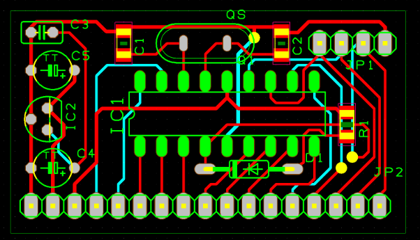
Understanding Basic PCB Design Principles
For beginners, the intricacies of PCB design can initially seem overwhelming. However, by concentrating on a few core principles, the entire process becomes significantly more manageable:
● Simplicity is Key: Start with single-layer PCB designs to avoid unnecessary complexity. The majority of smart home projects do not typically require multi-layer boards, simplifying both design and fabrication.
● Appropriate Trace Width: Ensure that electrical traces are dimensioned with sufficient width to safely handle the expected current flow. For example, a trace carrying 1A at 5V should be at least 0.5mm wide to prevent resistive heating and potential damage.
● Adequate Spacing: Maintain appropriate spacing between adjacent traces (a minimum of 0.2mm is generally recommended) to effectively prevent unintended short circuits.
● Ground Plane Implementation: Incorporate a dedicated ground plane into your design. This is especially crucial for projects involving microcontrollers like Raspberry Pi, as it significantly reduces electrical noise and improves overall signal integrity, making the system more stable and reliable.
Easy PCB Projects for DIY Smart Home Automation
With a foundational understanding of PCB design established, let’s explore several straightforward PCB projects perfectly suited for smart home applications. These projects leverage beginner-friendly platforms such as Arduino and Raspberry Pi, making them ideal for developing practical skills while building genuinely useful smart home devices.
Project 1: Smart Light Controller with Arduino
Overview: This project focuses on designing a PCB to control a room's lighting system using an Arduino microcontroller. The system will automate lighting functions, such as turning lights on or off based on input from a motion sensor.
Components Needed:
● Arduino Nano (or a compatible equivalent)
● PIR (Passive Infrared) motion sensor
● Relay module (e.g., 5V, rated for 10A)
● Resistors (e.g., 220Ω for current limiting LEDs)
● Capacitors (e.g., 10uF for power supply decoupling)
Steps to Design and Build:
1. Develop the circuit schematic in your chosen design software. Connect the PIR sensor’s output to a digital input pin on the Arduino (e.g., D2) and the relay module’s input to another digital pin (e.g., D3).
2. Design the PCB layout, positioning the Arduino Nano centrally and routing electrical traces to connect the sensor and relay. Ensure that power traces (e.g., 5V lines) are at least 0.5mm wide for safety.
3. Export the finalized design files and arrange for PCB manufacturing through a reputable service.
4. Carefully solder all components onto the fabricated PCB, paying close attention to correct polarity for components like capacitors and diodes.
5. Upload a straightforward Arduino sketch (program) that detects motion and subsequently activates the relay, which then controls a 220V AC light fixture. (Always exercise extreme caution when working with high-voltage AC circuits.)
Technical Tip: Verify that the chosen relay's current rating safely exceeds the current drawn by your light fixture. For instance, a 100W light bulb operating at 220V draws approximately 0.45A, so a 10A-rated relay provides a substantial safety margin.
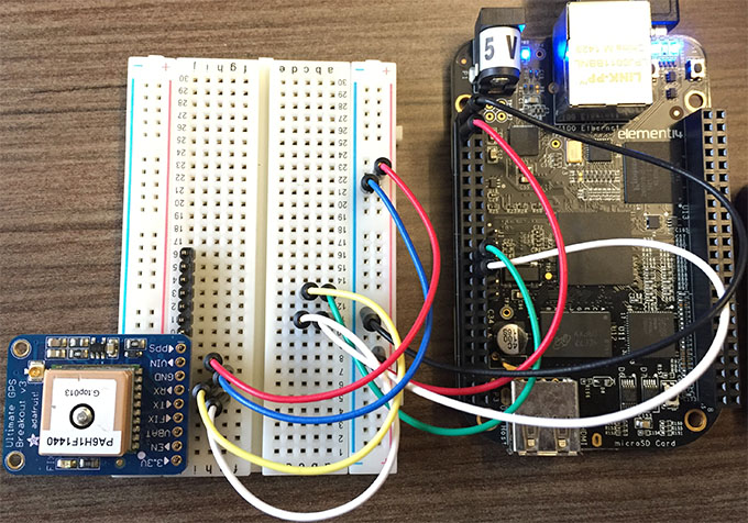
Project 2: Temperature Monitor with Raspberry Pi
Overview: This project involves constructing a PCB to accurately monitor room temperature using a Raspberry Pi and a digital temperature sensor. The collected data can then be displayed on a small screen or transmitted to your smartphone via Wi-Fi.
Components Needed:
● Raspberry Pi (any model equipped with GPIO pins)
● DHT22 temperature and humidity sensor
● OLED display (e.g., 128x64 pixels, I2C interface)
● Resistors (e.g., 4.7kΩ for pull-up on the sensor data line)
Steps to Design and Build:
1. Create the schematic, connecting the DHT22 sensor's data pin to a GPIO pin on the Raspberry Pi (e.g., GPIO4). Include a 4.7kΩ pull-up resistor connected to the 3.3V line.
2. Design the PCB layout, ensuring that the I2C communication lines to the OLED display are kept as short as possible (ideally under 10cm) to minimize potential signal noise and interference.
3. Arrange for PCB manufacturing and meticulously assemble all components, double-checking all pin alignments.
4. Program the Raspberry Pi using Python code to read temperature data at regular intervals (e.g., every 5 seconds) and display it clearly on the OLED screen.
Technical Tip: While the DHT22 sensor can operate from 3.3V to 5V, it is crucial to power it with 3.3V when interfacing with a Raspberry Pi to prevent potential damage to the sensitive GPIO pins. Data transfer speed for this sensor is relatively low (around 1Hz), so trace length is generally not a critical concern unless electromagnetic interference is particularly high.
Project 3: Smart Door Lock Control with Arduino
Overview: This project involves designing a PCB to control a smart door lock mechanism using an Arduino and a servo motor. The system can be further enhanced with additional security features such as an RFID reader or a numerical keypad.
Components Needed:
● Arduino Uno or Nano
● Servo motor (e.g., 5V, maximum 1A current draw)
● Push button or an RFID module
● Resistors (e.g., 1kΩ for a button pull-down configuration)
Steps to Design and Build:
1. In your schematic, connect the servo motor’s control pin to a PWM (Pulse Width Modulation) pin on the Arduino (e.g., D9) and the push button’s output to a digital input pin (e.g., D4).
2. Lay out the PCB with a dedicated, wider power trace for the servo motor (e.g., 0.8mm width) to safely handle its potentially high current draw, especially during startup.
3. Manufacture and assemble the PCB, ensuring the servo motor connector is securely attached and correctly wired.
4. Program the Arduino to rotate the servo motor by 90 degrees, effectively unlocking the door mechanism, when the push button is activated.
Technical Tip: Servo motors can momentarily draw significant current (up to 1A at 5V during initial startup). To mitigate potential voltage drops and prevent the Arduino from resetting, it is advisable to include a large decoupling capacitor (e.g., 100uF) positioned close to the servo's power input pin.
Tips for Success in DIY Smart Home PCB Projects
As you progress through your journey in PCB design for smart home projects, keeping these practical tips in mind will ensure smoother progress and a higher likelihood of success:
Strategic Project Planning
● Start Small: Always begin with easy, manageable PCB projects. This approach helps build confidence and foundational skills before tackling more complex designs involving multiple sensors or advanced wireless communication modules.
● Thorough Testing: Before applying full power to your project, use a multimeter to meticulously check for electrical continuity and verify correct voltage levels (e.g., ensuring 5V or 3.3V at microcontroller pins). This prevents costly damage from incorrect wiring.
● Safety First: When working with components that handle high AC voltages, such as relays, always ensure proper electrical insulation. Crucially, never attempt to work on live circuits to avoid electric shock.
● Comprehensive Documentation: Maintain detailed notes on your schematic designs, PCB layouts, and program code. This practice is invaluable for future troubleshooting, making modifications, or replicating the project accurately.
● Iterative Improvement: Recognize that your initial PCB designs may not be perfect. Embrace mistakes—such as incorrect trace widths or suboptimal component placements—as learning opportunities and continuously refine your designs through iterative improvements.
Common Challenges for PCB Design Beginners and Solutions
Newcomers often encounter specific hurdles when they first venture into PCB design. Here are some prevalent issues and their practical solutions:
Component Footprint Mismatch
Challenge: Physically assembling components only to discover their footprints on the PCB do not match (e.g., a 0805 resistor footprint used instead of a 0603).
Solution: Always double-check and verify component footprints within your design software against the physical dimensions of the actual parts you intend to use. Most component datasheets provide precise footprint recommendations.
Signal Interference
Challenge: Your Arduino or Raspberry Pi project experiences erratic behavior, glitches, or unreliable sensor readings, often due to electrical noise.
Solution: Implement a robust ground plane in your PCB layout. Additionally, keep sensitive traces (such as those for I2C or SPI communication) as short as physically possible (ideally under 5cm if feasible) to minimize their susceptibility to external interference.
Overheating Traces
Challenge: Electrical traces on your PCB become excessively hot or even burn out due to insufficient current-carrying capacity.
Solution: Before finalizing your layout, use online trace width calculators. Input parameters like desired current, acceptable temperature rise, and copper thickness (e.g., 1oz copper). For a 2A load at 5V, a trace should typically be at least 1mm wide to safely dissipate heat.
Expanding Your DIY Smart Home Projects
Once you've gained confidence with basic PCB projects, consider enhancing your smart home system with more advanced functionalities:
Advanced Features
● Wireless Control Integration: Add Wi-Fi or Bluetooth modules to your designs. This enables remote control of your smart devices directly from your smartphone or other connected platforms.
● Centralized System Integration: Design a central hub PCB that can integrate and manage multiple individual PCBs, consolidating control over lights, temperature, security, and other smart home functions into a single interface.
● Energy Monitoring Capabilities: Develop a PCB incorporating current sensors to precisely track the power consumption of various appliances. This feature can provide valuable data, helping you identify areas for energy savings.
Conclusion: Start Building Your Smart Home Today
DIY smart home PCB projects offer an incredibly engaging and rewarding pathway to infuse automation and convenience into your daily life, all while acquiring invaluable electronics design skills. Leveraging accessible platforms like Arduino and Raspberry Pi, even beginners can conceptualize and build powerful, bespoke smart home solutions through a series of easy PCB projects. By commencing with straightforward designs and progressively tackling more intricate systems, you will steadily progress toward creating a comprehensively automated home perfectly tailored to your unique preferences and needs.
At AIVON, we are deeply committed to supporting your journey in PCB design and manufacturing. Whether your current endeavor involves a basic smart light controller or a more complex temperature monitoring system, our services are geared towards delivering high-quality, precision-fabricated boards that effectively bring your innovative ideas to fruition. Embark on your PCB design journey for beginners today, and watch as your smart home aspirations transform into tangible reality!


