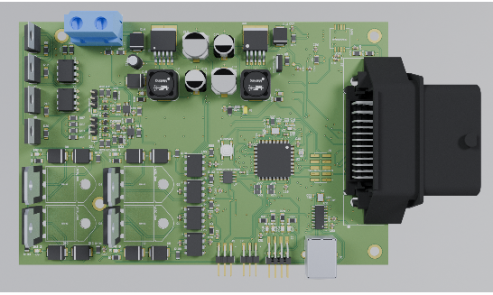
Why Is Repairing an ECU PCB Important for Vehicle Performance?
The Engine Control Unit (ECU) functions as the central nervous system of a modern vehicle, orchestrating critical operations such as fuel delivery, ignition timing, and exhaust emissions. When the Printed Circuit Board (PCB) within the ECU malfunctions, it can trigger significant performance issues or even render the vehicle inoperable. Opting to repair a faulty ECU PCB yourself can present a highly economical alternative to purchasing a new replacement, which often involves substantial costs.
However, undertaking such repairs without the appropriate tools risks further damage or results in an incomplete fix. By assembling a well-equipped DIY PCB repair kit, you can effectively tackle common problems like compromised solder joints, damaged conductive traces, or defective electronic components, restoring your vehicle's functionality.
What Essential Tools Should Be in Your DIY PCB Repair Kit?
Before embarking on any repair, it's crucial to gather the right set of instruments. A comprehensive DIY PCB repair kit ensures you have the necessary means to accurately diagnose, skillfully repair, and thoroughly test an ECU PCB. Each item serves a specific function in the intricate process of electronics repair.
The Soldering Iron: Your Primary Connection Tool
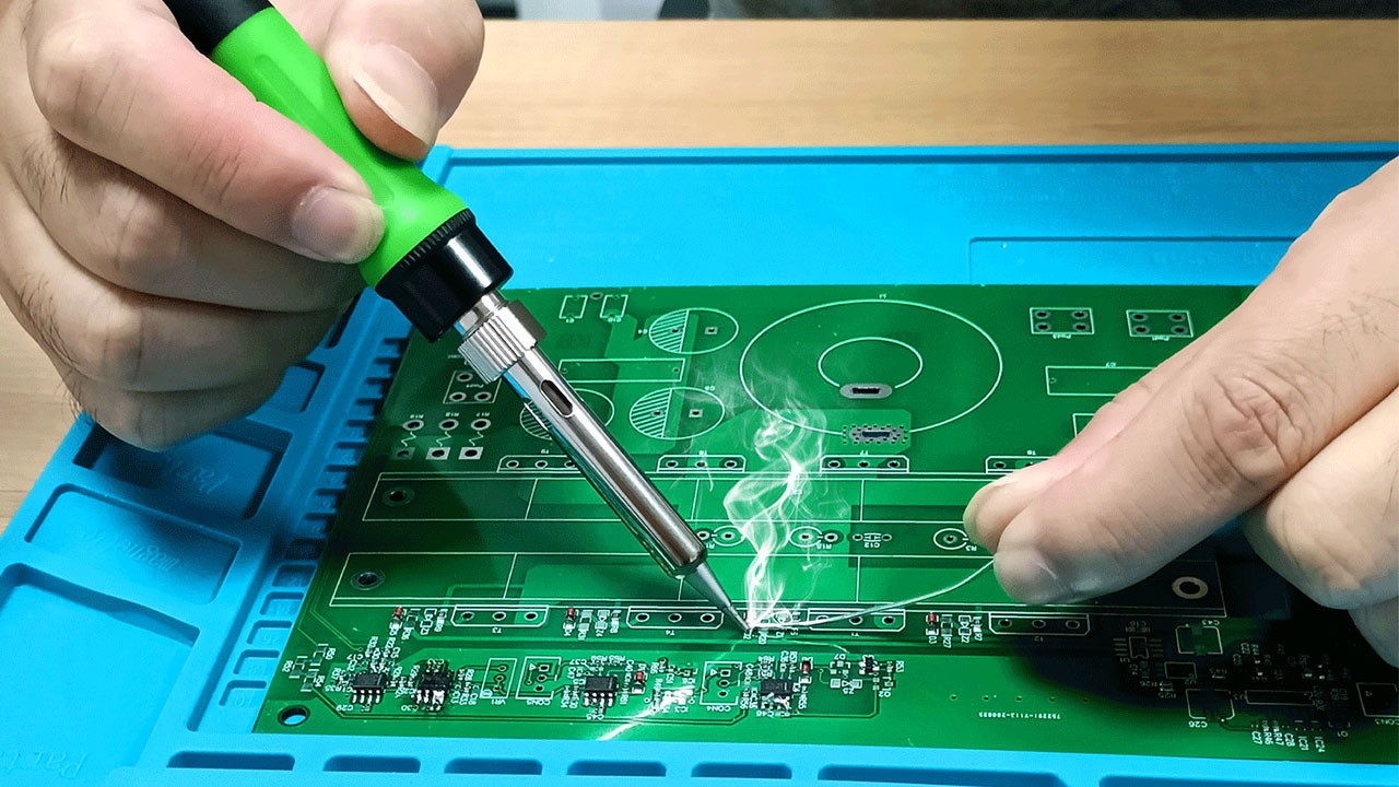
A soldering iron stands as the fundamental instrument for any PCB repair. Its purpose is to melt solder, a metallic alloy that forms electrical connections between components and the circuit board. For ECU PCB repairs, selecting a soldering iron with precise temperature control is vital to prevent thermal damage to sensitive electronic parts.
Key Features to Prioritize:
● Temperature Regulation: An iron with adjustable temperature settings, ideally ranging from 300°C to 400°C (572°F to 752°F), provides the versatility needed for different solder types and components.
● Fine Tip: A narrow tip, between 0.5mm and 1mm, is indispensable for precision work on the compact, densely populated surfaces of ECU PCBs.
● Optimal Wattage: A soldering iron with 25W to 40W generally supplies sufficient heat for most PCB tasks without posing a risk of overheating.
How to Use It Effectively:
Preheat the iron to the suitable temperature. Apply a small amount of flux to the joint to improve solder flow. Briefly touch the iron's tip to the joint while introducing solder wire. Work quickly—aim for a contact time of 2-3 seconds per joint—to avoid overheating components. Always keep the soldering iron tip clean using a damp sponge or specialized cleaner after each use to prevent oxidation, which can impede proper heat transfer and connection quality.
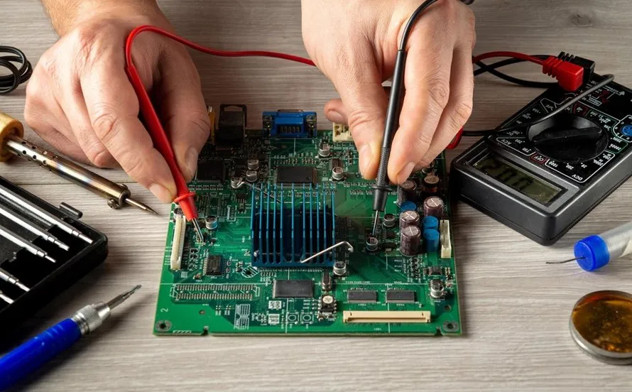
The Multimeter: Your Diagnostic Companion
An electronic multimeter is an indispensable tool for diagnosing problems on an ECU PCB. It allows you to measure voltage, current, and resistance, helping to pinpoint faults such as short circuits, open circuits, or failing components.
Key Features to Prioritize:
● Digital Display: A digital multimeter (DMM) offers highly accurate numerical readings, superior to older analog models.
● Continuity Test: This invaluable feature emits an audible signal when a circuit is complete, simplifying the detection of broken traces or faulty connections.
● Voltage Range: Ensure the device can measure DC voltage up to at least 20V, as most automotive ECUs operate within 12V systems.
How to Use It Effectively:
Select the appropriate mode on the multimeter (e.g., DC voltage or continuity). For voltage checks, place the probes on the positive and negative points of a circuit; typical ECU lines should show readings around 5V or 12V. For continuity, touch the probes to two points to confirm an electrical connection; the absence of a beep indicates a broken circuit. Always double-check your probe placement to prevent accidental short circuits. For instance, a voltage reading below 4.5V on a 5V line often signals a faulty voltage regulator or capacitor.
Desoldering Tools: For Component Removal
Desoldering tools are essential for safely removing old or damaged components from an ECU PCB without causing harm to the board. These instruments facilitate the extraction of solder from joints, enabling the replacement of defective parts like resistors, capacitors, or integrated circuit (IC) chips.
Types of Desoldering Tools:
● Desoldering Pump (Solder Sucker): An inexpensive, manual tool that uses a spring-loaded vacuum to draw molten solder away. It's a great starting point for beginners.
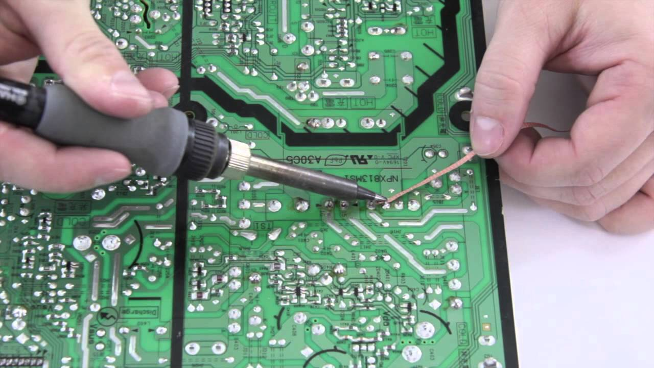
● Desoldering Wick (Braid): A finely braided copper wire designed to absorb molten solder when heated. Ideal for cleaning up small solder bridges or working in confined spaces.
● Desoldering Station: A more advanced system that combines a heated tip with an integrated vacuum pump for professional-grade solder removal. This is the preferred choice for frequent or high-volume repairs.
How to Use Them Effectively:
To use a desoldering pump, heat the solder joint until the solder liquefies, then quickly position the pump's nozzle over the molten solder and activate the suction. For desoldering wick, place the braid directly onto the solder joint, apply heat with your soldering iron, and watch as the solder wicks into the braid. Always exercise caution to avoid overheating the PCB pads, as the delicate traces on ECU boards can easily lift and become damaged. Integrating flux with desoldering wick can significantly enhance solder absorption and further protect the board from damage.
Flux and Solder Wire: The Bonding Agents
Flux is a chemical compound that cleans and primes surfaces for soldering by eliminating oxidation, thereby ensuring robust and reliable electrical connections. Solder wire is the fusible metal alloy used to form these crucial electrical bonds.
Key Features to Prioritize:
● Flux Type: Opt for a "no-clean" flux for convenience, as it leaves minimal residue. Rosin-based flux is another widely accepted option in electronics repair.
● Solder Wire Composition & Diameter: For detailed PCB work, select lead-free solder with a diameter between 0.6mm and 1mm. If local regulations permit, a 63/37 tin-lead alloy is often preferred due to its lower melting point (around 183°C or 361°F).
How to Use Them Effectively:
Always apply flux to the joint before soldering or desoldering to enhance solder flow and adhesion. When feeding solder wire, use it sparingly to prevent excess material that could lead to unintended shorts. Proper storage of solder wire in a cool, dry environment is crucial to prevent oxidation, which can compromise the integrity of soldered joints.
Precision Screwdrivers and Tweezers: For Delicate Handling
Accessing the fast turn PCB within an ECU often requires careful disassembly of the unit. Precision screwdrivers are indispensable for removing tiny fasteners without stripping them, while fine-tip tweezers are perfect for manipulating small components like surface-mount resistors or capacitors with accuracy.
Key Features to Prioritize:
● Screwdrivers: A versatile set including various small-sized heads (e.g., Phillips, flathead, Torx, from 1.5mm to 3mm) will cover most requirements.
● Tweezers: Anti-static, fine-point tweezers are essential to prevent damage to sensitive components and guard against electrostatic discharge (ESD).
How to Use Them Effectively:
Employ precision screwdrivers to carefully open the ECU casing, taking care not to damage the screws or the housing. Tweezers are ideal for precisely positioning or removing small parts during the soldering process. To safeguard delicate ECU components from ESD, always work on an anti-static mat or wear an anti-static wrist strap.
Magnification Tools: For Detailed Inspection
ECU PCBs feature exceedingly small components and intricate traces that are often invisible to the naked eye. A magnifying glass or a digital microscope becomes invaluable for closely inspecting solder joints, identifying hairline cracks, or deciphering minuscule component markings.
Key Features to Prioritize:
● Magnification Level: A 5x to 10x magnifying glass is adequate for basic inspections. For more thorough examinations, a digital microscope offering 20x to 50x zoom, often with a dedicated screen, provides superior detail.
● Integrated Lighting: Built-in LED illumination significantly enhances visibility on darker circuit boards.
How to Use It Effectively:
Routinely inspect this type of HDI PCB both before and after repairs to identify issues such as "cold" solder joints (which appear dull or cracked) or lifted pads. Pairing your magnification tool with a stable work surface ensures the PCB remains steady during these critical inspections.
What Advanced Tools Can Enhance ECU PCB Repair?
Beyond the fundamental tools, certain specialized instruments can significantly streamline more complex repairs, proving especially beneficial for professionals or frequent DIY enthusiasts.
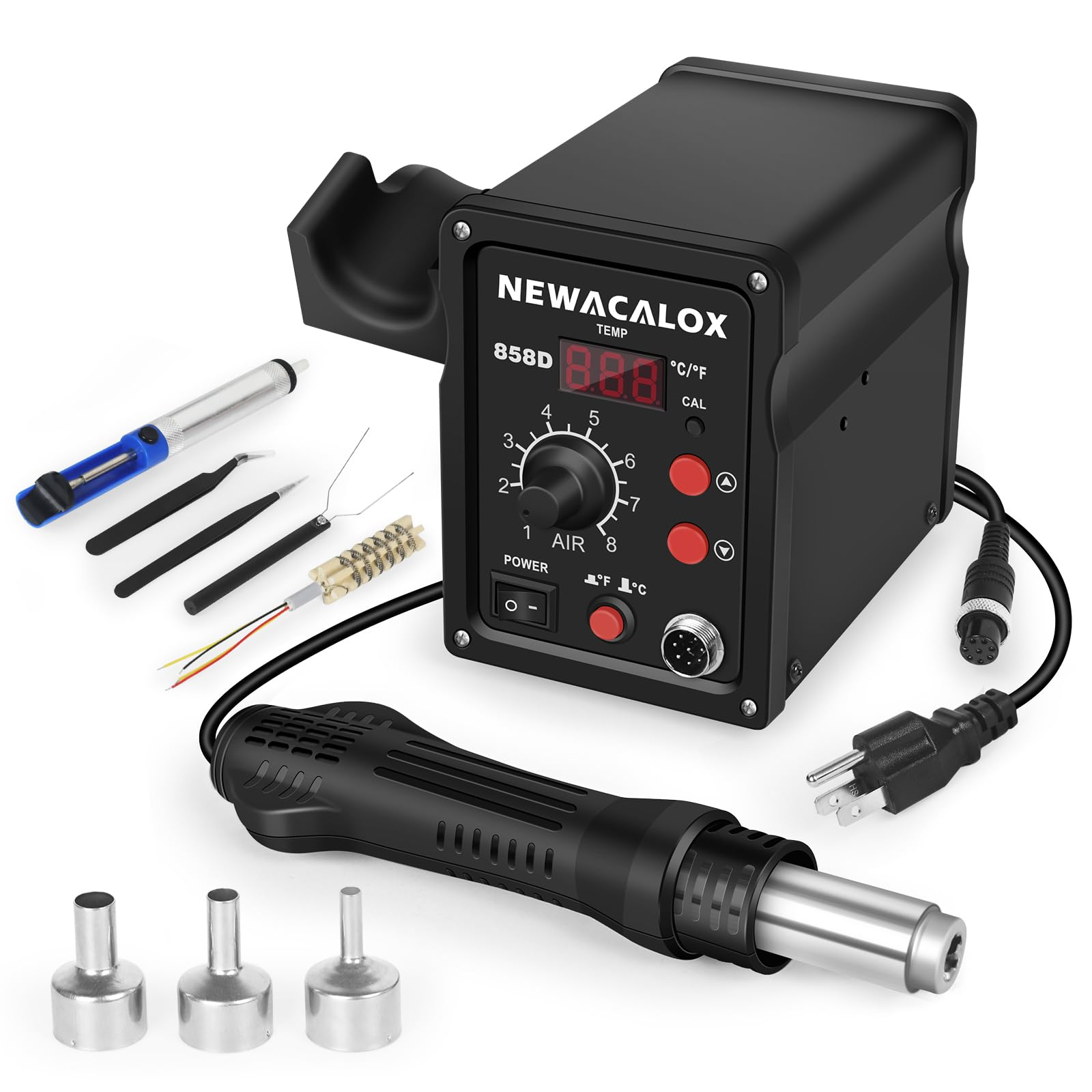
● Hot Air Rework Station: This device uses precisely controlled hot air to remove or reflow surface-mount components (SMDs). It is particularly useful for replacing integrated circuit (IC) chips on ECU PCBs. Look for models offering adjustable temperature settings (from 100°C to 500°C or 212°F to 932°F) and variable airflow control for precise application.
● PCB Holder or "Third Hand": This apparatus securely holds the circuit board in place while you work, often featuring adjustable arms and integrated magnifying lenses. It frees up your hands, allowing for greater precision and stability during intricate soldering tasks.
● Cleaning Supplies: High-purity isopropyl alcohol (90% or higher concentration) combined with a soft brush is essential for effectively removing flux residue and any dirt or contaminants from the PCB surface after soldering, ensuring clean connections and preventing potential issues.
Step-by-Step ECU PCB Repair with Your DIY Kit
Once your DIY PCB repair kit is assembled, you can confidently approach a typical ECU PCB repair following these steps:
1. Diagnose the Problem: Begin by using your multimeter to check for power anomalies, short circuits, or broken traces. Pay attention to voltage drops (e.g., below 4.5V on a 5V line) or a lack of continuity where an electrical connection should exist.
2. Disassemble the ECU: Carefully open the ECU casing using your precision screwdrivers. Exercise extreme caution to prevent electrostatic discharge (ESD) damage to sensitive internal components.
3. Inspect the Circuit Board: Utilize a magnifying glass or microscope to visually examine the PCB for any signs of damage, such as burnt components, cracked solder joints, or lifted traces.
4. Remove Defective Components: Employ your desoldering tools to extract any faulty parts. Apply flux, heat the joint until the solder melts, and then use either a desoldering pump or wick to clear the solder.
5. Install New Components: Position the replacement component, apply fresh flux, and use your soldering iron to create strong, clean solder joints.
6. Clean and Test: Thoroughly clean the repaired area of the board with isopropyl alcohol. Afterward, use your multimeter to verify all new connections and confirm correct voltage readings (e.g., 5V for logic circuits).
7. Reassemble and Test in Vehicle: Carefully reassemble the ECU unit and reinstall it in the vehicle. Conduct a thorough test to ensure proper operation.
Always work in a well-ventilated space when soldering to avoid inhaling fumes, and wear safety glasses to protect your eyes from accidental solder splatter.
Crucial Safety Precautions for ECU PCB Repair
Undertaking ECU PCB repairs involves working with heat, various chemicals, and delicate electronics, making safety paramount.
● Always work on a non-conductive, heat-resistant surface to prevent short circuits or accidental burns.
● Implement anti-static protection, such as an anti-static mat and wrist strap, to safeguard sensitive components from damage caused by electrostatic discharge (ESD).
● Keep hot soldering tools away from any flammable materials, as soldering iron tips can reach temperatures exceeding 300°C (572°F).
● Thoroughly wash your hands after handling solder or flux to minimize exposure to potentially harmful substances.
Empowering Your Repairs with the Correct ECU PCB Tools
Successfully repairing an ECU PCB can be a highly rewarding and cost-effective endeavor, provided you have the right tools in your DIY PCB repair kit. From a dependable soldering iron to an accurate multimeter and efficient desoldering equipment, each item plays a critical role in diagnosing and resolving electronic issues. By investing in quality ECU PCB repair tools and consistently adhering to safe practices, you can confidently address common problems like solder joint failures or component damage.
Begin by honing your skills on scrap circuit boards, gradually progressing to more intricate repairs as your expertise grows. With the comprehensive tools and practical tips outlined in this guide, you are well-prepared to master ECU PCB repair. Maintain an organized kit, cultivate patience, and relish the satisfaction of revitalizing complex electronics.


