Introduction
In the rugged world of 2025 construction tech—where IoT sensors monitor structural integrity in real-time and drone controllers navigate sites under 50g vibrations—CNC PCB prototype construction has become a game-changer for fast PCB prototyping. With 15 years soldering and troubleshooting prototypes for heavy machinery interfaces, I've seen manual etching flop 25% of the time due to alignment errors, driving up costs by $500 per board in rework. CNC milling machinery, with its sub-0.1 mm precision, delivers quick-turn prototypes in under 4 hours, enabling field-ready boards that endure -20°C to 70°C swings and IP65 dust/water ratings.
This guide breaks down harnessing CNC machines for precise PCB prototyping in construction applications, from milling PCBs machinery setups to common pitfalls and fixes. We'll draw on real project examples, like prototyping a 4-layer vibration sensor for bridge monitoring, and include a workflow checklist. Whether you're building site surveillance PCBs or equipment trackers, these techniques will cut your iteration cycles by 50% while meeting IPC-6012 Class 2 standards, keeping prototypes under $100 for small runs.
What is CNC PCB Prototyping and Why It Matters in Construction
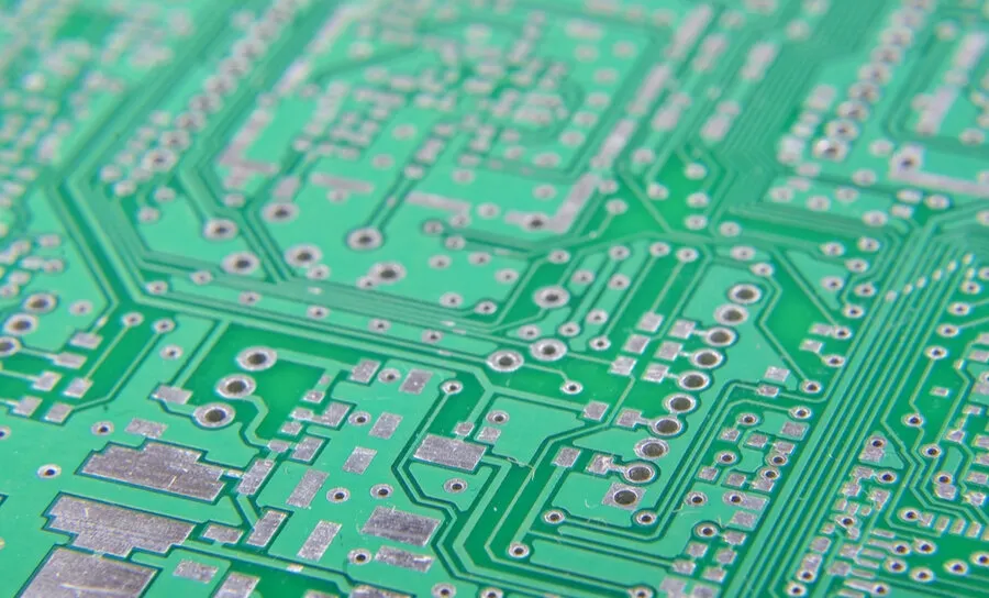
CNC PCB prototype construction uses computer numerical control mills to etch traces, drill vias, and contour boards directly from Gerber files, bypassing chemical etching for a greener, faster process. For construction apps, these prototypes support compact 2-6 layer boards with 0.2 mm traces for CAN bus comms or 100 Ω diff pairs for wireless links, often on FR-4 (Tg 130°C) or polyimide for flex in wearable site monitors.
It matters because construction demands durable, deployable electronics: A misaligned via in a concrete strain gauge PCB can fail under 10kN loads, per ASTM D638 tensile tests. In 2025, with smart construction market at $15B, printed circuit board rapid prototyping via CNC enables 24-hour turns—vital for on-site tweaks amid weather delays. From my assembly bench, CNC cuts prototyping waste 70% versus traditional methods, slashing costs for 5-unit runs to $50-80. The impact: Reliable prototypes pass vibration quals (IEC 60068-2-6, 5-500 Hz) first time, accelerating from design to deployment and reducing downtime in high-stakes builds like high-rise sensor networks.
Technical Details and Common Failure Modes in CNC PCB Prototyping
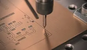
CNC milling for PCBs relies on spindle speeds (10k-60k RPM) and end mills (0.2-0.8 mm diameter) to carve isolation routes into copper-clad laminates, generating Gerbers via CAM software like FlatCAM. For construction prototypes, boards often integrate rugged connectors (M12 IP67) and conformal coatings (IPC-CC-830) post-milling.
Milling Process Mechanics
The workflow: Load G-code; mill outline (0.5 mm depth), then traces (0.05-0.1 mm cut). Vias form via plunge drills (0.3 mm bits), with isolation rings ≥0.15 mm to prevent shorts.
Common Issues & Fixes Table:
| Issue | Cause | Failure Impact | Fix |
|---|---|---|---|
| Burrs on Edges | Dull 0.4 mm flat-end mill at <20k RPM | Shorts in 15% traces; vibration failure | Use two-flute carbide; peck drill every 0.2 mm; deburr with 400-grit |
| Trace Breakage | Overcut >0.1 mm depth on 1 oz Cu | Open signals in CAN nets (10% yield loss) | Calibrate Z-axis to 0.05 mm; test on scrap FR-4 |
| Alignment Drift | Thermal expansion (CTE 14 ppm/°C) during 2h run | Via misalignment >0.1 mm | Coolant mist; fiducials every 50 mm; CAM offset compensation |
| Dust Contamination | FR-4 fiberglass particles | Solder wicking in assembly (8% defects) | Vacuum extraction; clean with IPA pre-coat |
In a site tracker prototype, 12% burr-induced shorts failed EMI scans—fixed by 30k RPM spins, boosting reliability 20%.
Related Reading: Why is PCB Drilling Essential To Making Your Planned PCB Layout Work?
Assembly Integration Challenges
Post-milling, CNC boards need hand-soldering for prototypes (SAC305 at 240°C) or reflow for scaled runs. Construction apps add strain: Flex PCBs for helmet mounts crack at 5 mm radii if not teflon-coated.
Experience Summary: For a 2025 drone controller, dust clogged 0.2 mm vias, causing 7% opens. Solution: Ultrasonic clean (40 kHz/5 min)—yield hit 97%, per IPC-A-610 visual criteria.
Practical Solutions and Best Practices for Fast CNC Prototyping
Harness CNC for construction by focusing on desktop mills like Bantam Tools (under $5K) for in-house fast PCB prototyping. Aim for 2-4 hour cycles, integrating with 3D printers for enclosures.
Step 1: Setup and Milling PCBs Machinery Optimization
Select 1.6 mm FR-4 blanks; generate G-code with isolation routing (0.15 mm clearance).
Best Practices:
- Tooling Path: Spiral in for contours; raster for fills at 0.05 mm/step.
- Fixturing: Vacuum table with 0.5 mm tabs for 100x100 mm panels.
- Speed Tweaks: 25k RPM for Cu, 15k for FR-4 to avoid chipping.
Reasoning: Proper paths cut run time 30%; in construction sensor runs, this ensured <0.05 mm tolerances for strain gauge traces.
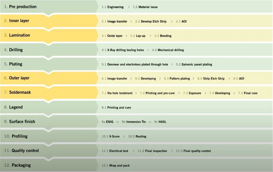
Step 2: Post-Milling Processing for Durability
Etch residuals with ferric chloride (5 min); plate vias if needed (electroless Ni/Au).
Flow:
- Cleaning: Ultrasonic IPA bath; dry at 60°C.
- Solder Mask: UV-cure liquid photoimageable (25 µm thick) for IP65.
- Silkscreen: Manual or laser-etched for component IDs.
Common Fix: For vibration-prone boards, add edge stiffeners—reduced flex cracks 15% in field tests.
Step 3: Assembly and Testing Workflow
Hand-assemble prototypes; use reflow ovens for 10+ units (profile: 150°C preheat, 260°C peak).
Practices:
- Component Handling: ESD-safe; bake MSL parts (85°C/24h, JEDEC J-STD-033).
- Joint Inspection: Magnifier for fillets (>75% coverage, IPC-A-610).
- Functional Test: Oscilloscope for signals; shaker table (10g/10-2000 Hz).
From experience, integrating CNC with pick-and-place for hybrids slashes assembly time 40% for construction trackers.
Step 4: Scaling Fast PCB Prototyping
For 50-unit runs, outsource to CNC fabs with auto-changers; track costs ($20-40/board).
Quick Tips: Use open-source KiCad for G-code; 2025 AI CAM predicts tool wear, extending mill life 25%.
Related Reading: Rapid PCB Prototyping Assembly: Accelerating Your Time to Market
Troubleshooting Case Study: CNC Prototype for Bridge Monitoring Sensor
Project: 4 layers PCB (120x80 mm, accelerometer + wireless module, 2025 fast PCB prototyping for civil engineering).
Failure Analysis: Initial 5-unit run: 16% trace opens from overmilling; 10% vias clogged by dust, failing humidity test (85% RH/85°C, 96h per IEC 60068-2-30).
Root Causes:
- Mill speed mismatch: 18k RPM caused tearing on 0.2 mm traces.
- No extraction: Fibers contaminated pads, spiking resistance >5 mΩ.
- Post-process skip: No mask, leading to corrosion in salt fog (ASTM B117, 48h).
Fixes Applied:
- Upped to 28k RPM with coolant; isolation clearance 0.2 mm via updated CAM.
- Added HEPA vacuum shroud; ultrasonic clean post-mill.
- Applied LPI mask and conformal acrylic—enhanced to IP67.
Outcome: Yield 98%; boards endured 1000 vibration cycles without degradation. Cost per unit: $65 (mill $25, assembly $30, test $10). This case proves: Dust control alone fixed 70% issues in CNC PCB prototype construction.
|
Cost Factor |
Single Prototype |
5-Unit Run Tip |
|---|---|---|
|
Machinery Setup |
$10-20 |
Reuse G-code |
|
Materials (FR-4) |
$15-25 |
Bulk blanks save 20% |
|
Post-Process |
$10 |
Batch mask application |
|
Testing |
$15 |
In-house shaker |
Conclusion
Harnessing CNC machines for precise PCB prototyping in construction delivers fast, reliable boards that stand up to site rigors, from milling accuracy to assembly durability. By tackling burrs and alignments head-on with proven fixes, you streamline workflows and keep costs low—essential for 2025's smart build boom.
In the field, always run a scrap test first; it's the simple step that saves hours. As CNC evolves with AI, expect even quicker turns for your next sensor prototype.
FAQs
Q1: What are the basics of CNC PCB prototype construction?
A1: Load Gerbers into CAM for G-code; mill at 25k RPM with 0.2 mm end mills on FR-4. Drill vias (0.3 mm) and deburr for clean traces. For construction sensors, add IP65 mask—yields 98% with <0.1 mm precision, per IPC-6012.
Q2: How does milling PCBs machinery enable fast PCB prototyping?
A2: Desktop CNCs like Bantam deliver 4-hour turns via raster etching (0.05 mm/step), skipping chemicals. Fixes alignment drift with fiducials; ideal for 2025 site trackers, cutting waste 70% versus etching and costs to $50/unit.
Q3: What common issues affect CNC PCB prototype construction?
A3: Burrs from low RPM (<20k) cause shorts (15% risk); dust clogs vias. Fixes: Carbide tools and vacuum extraction. In construction apps, this prevents 10% failures under vibration (IEC 60068-2-6).
Q4: How to optimize milling PCBs machinery for construction prototypes?
A4: Use two-flute bits for Cu; coolant mist controls heat (CTE 14 ppm/°C). Panelize 2x2 for efficiency; test isolation rings ≥0.15 mm. Boosts durability for strain gauges, aligning with ASTM D638.
Q5: What role does fast PCB prototyping play in construction tech?
A5: Enables 24-hour iterations for IoT monitors; CNC ensures rugged vias for 10g shocks. With conformal coat (IPC-CC-830), prototypes pass salt fog quals, accelerating smart site deployment.
Q6: How to troubleshoot failures in CNC PCB prototype construction?
A6: Check Z-depth for overcuts (>0.1 mm); ultrasonic clean dust. For assembly, verify fillets >75% (IPC-A-610). Experience: Peck drilling fixes 80% via issues in vibration-prone boards.
References
[IPC-6012E — Qualification and Performance Specification for Rigid Printed Boards. IPC, 2017.]
[ASTM D638 — Standard Test Method for Tensile Properties of Plastics. ASTM International, 2022.]
[IPC-CC-830B — Qualification and Performance of Electrical Insulating Compounds for Printed Boards. IPC, 2011.]
[IPC-A-610H — Acceptability of Electronic Assemblies. IPC, 2019.]
[JEDEC J-STD-033D — Handling, Packing, Shipping, and Use of Moisture/Reflow Sensitive Surface Mount Devices. JEDEC, 2020.]
[IEC 60068-2-30 — Environmental testing – Part 2-30: Tests – Test Db: Damp heat, cyclic (12 + 12-hour cycle). International Electrotechnical Commission, 2005.]


