Why Assemble or Repair Your Own Security Camera PCB?
If you're interested in constructing or repairing a security camera by soldering and assembling its printed circuit board (PCB), this guide will provide a structured approach. It offers a step-by-step methodology for security camera PCB soldering and CCTV PCB assembly, empowering you to create a functional and dependable surveillance system. This detailed tutorial covers everything from the necessary tools for soldering components onto a camera PCB to best practices for board assembly, alongside actionable DIY electronics assembly tips.
Security cameras are indispensable for monitoring various environments, from private residences to public spaces. While off-the-shelf cameras are readily available, undertaking the assembly or repair of a CCTV system's PCB offers several distinct advantages. It provides opportunities for customization, potential PCB board cost savings, and a deeper understanding of the underlying technology. By mastering security camera PCB soldering, you can tailor critical features—such as resolution, night vision capabilities, or specific functionalities—to precisely meet your requirements. Beyond customization, engaging in a CCTV PCB assembly project cultivates valuable electronics skills. This guide will equip you with the knowledge to confidently handle tasks ranging from replacing a faulty component to building a camera from scratch.
Essential Tools and Materials for Security Camera PCB Soldering
Before commencing any soldering or assembly work, it is crucial to gather all necessary tools and materials. Having everything prepared beforehand will ensure a smoother process and minimize interruptions. Here is a list of essential items for soldering components onto a camera PCB:
Required Equipment
● Soldering Iron: Opt for a temperature-controlled soldering iron with a fine tip (approximately 1mm) to ensure precision. A 25-40 watt iron is typically ideal for PCB work.
● Solder Wire: Choose a lead-free solder wire with a rosin core, generally 0.8mm to 1mm in diameter, to facilitate clean and reliable joints.
● Desoldering Tools: A desoldering pump or desoldering wick will prove invaluable for correcting errors or removing existing components.
● Flux: Applying flux is essential for improving solder flow and ensuring robust, high-quality connections on the PCB.
● Multimeter: This instrument is indispensable for testing electrical connections and verifying voltage levels (e.g., confirming a 12V DC input, which is standard for most security cameras).
● Tweezers: Precision tweezers are crucial for accurately placing small surface-mount components like resistors or capacitors onto the board.
● Magnifying Glass or Loupe: These tools are highly beneficial for inspecting minute solder joints and verifying precise component placement.
● PCB and Components: Ensure you have the correct PCB layout specifically designed for your security camera, along with all required components, including the image sensor, resistors, capacitors, and various connectors.
● Safety Gear: Always wear safety glasses to protect your eyes from solder splashes, and work in a well-ventilated area to avoid inhaling soldering fumes.
Understanding the Security Camera PCB Layout
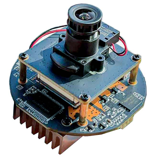
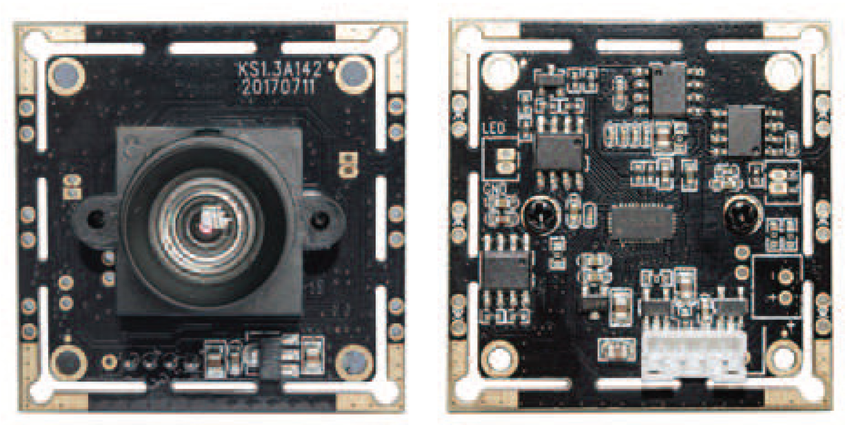
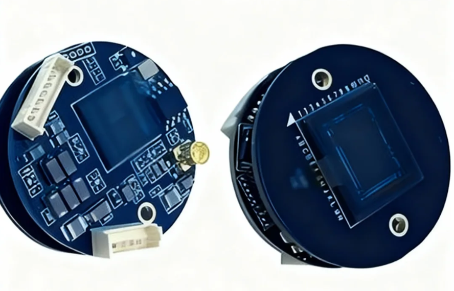
Prior to initiating the soldering process, it is important to familiarize yourself with the specific PCB layout designed for your security camera. Most camera PCBs are typically organized into distinct sections for the image sensor, power supply circuitry, signal processing unit, and various output connectors.
Key Component Areas
● Image Sensor: This is the core component of the camera, usually a CMOS or CCD sensor, responsible for capturing video data.
● Power Regulation Circuitry: This section converts the camera's input voltage (commonly 12V DC) into the lower voltages (e.g., 3.3V or 5V) required by the various components on the board.
● Signal Processing Chip: This integrated circuit processes the raw data received from the image sensor, transforming it into a usable video signal.
● Connectors: These ports facilitate power input, video output (e.g., BNC or RCA for analog, or Ethernet for IP cameras), and sometimes other functionalities.
Always consult the schematic or diagram provided with your PCB to accurately identify the placement of each component. If you are designing a custom board, ensure that the impedance of critical traces (e.g., 75 ohms for analog video signal lines) meets specified requirements to prevent signal loss or degradation.
A Step-by-Step Guide to Soldering Components onto a Camera PCB
With the necessary tools and a clear understanding of the PCB layout, we can now proceed with the process of soldering components onto your camera PCB. Meticulously following these steps will ensure a successful build.
Soldering Procedure
1. Prepare Your Workspace: Establish a clean, brightly lit, and well-ventilated workspace. Secure the PCB firmly using a holder or on a stable, flat surface to prevent any movement during soldering. Ensure your soldering iron is preheated to the correct temperature (approximately 300°C or 572°F for most components) to prevent thermal damage to the board or components.
2. Begin with Low-Profile Components: Start by soldering smaller, flatter components such as resistors and capacitors. Place each component into its designated position on the PCB, carefully aligning its leads with the corresponding pads. Apply a small quantity of flux to the pads, then simultaneously touch the soldering iron tip to both the pad and the component lead while feeding solder wire. Aim for a shiny, cone-shaped joint. Avoid excessive solder, as this can lead to short circuits. For instance, when soldering a 1kΩ resistor in a power regulation circuit, verify that the color bands match the schematic before placement. For a typical 10μF electrolytic capacitor used for voltage smoothing, ensure correct polarity during installation.
3. Advance to Larger Components: After securing the smaller components, move on to larger items such as connectors, Integrated Circuits (ICs), and the image sensor. For SMD pcb, consider using a hot air rework station or a drag soldering technique with flux to efficiently attach multiple pins simultaneously. For through-hole components, insert the leads through their respective holes, solder each pin, and then trim any excess lead material using wire cutters.
4. Inspect and Clean Solder Joints: Once all components have been soldered, meticulously inspect each joint under a magnifying glass. Look for any "cold joints" (which appear dull and grainy) or "solder bridges" (where solder connects unintended pads). Use a desoldering pump or wick to correct any identified issues. Finally, clean the PCB thoroughly with isopropyl alcohol and a brush to remove all flux residue, as this can cause corrosion over time.
CCTV PCB Assembly: Bringing the System to Life
With all components successfully soldered, the next phase involves assembling the PCB into a fully functional security camera system. Follow these steps for a complete CCTV PCB assembly.
System Assembly Steps
1. Test the Soldered PCB: Prior to full mechanical assembly, perform comprehensive electrical tests on the PCB to confirm all connections are correct and functional. Use a multimeter to check for continuity between pads and verify proper power delivery (e.g., 12V at the input and 3.3V at the sensor circuit). Connect a temporary power source and monitor any output signals to confirm the board operates as expected.
2. Mount the PCB in the Camera Housing: Carefully secure the PCB inside the camera's housing, ensuring that no wires or components make unintended contact with metal parts, which could cause shorts. Use appropriate standoffs or screws to firmly hold the board in place. Precisely align the image sensor with the lens mount to guarantee correct focus and field of view.
3. Connect External Components: Attach the lens securely to the image sensor mount. Connect the power and video output cables to their respective ports on the PCB. For analog cameras, utilize a BNC connector for video output, ensuring a 75-ohm impedance match to prevent signal degradation. For IP cameras, connect an Ethernet cable if applicable.
4. Final Testing and Calibration: Power on the fully assembled camera and test the video output by connecting it to a monitor or recording device. Adjust the lens focus as needed to achieve a sharp and clear image. Monitor for any issues such as flickering or image noise, which could indicate a soldering error, a power supply problem, or electromagnetic interference. If the camera incorporates infrared (IR) for night vision, test its functionality in low-light conditions to confirm proper activation of the IR LEDs.
Expert Tips for Successful Security Camera PCB Construction
To ensure your project proceeds smoothly and yields a high-quality product, keep these security camera PCB building tips in mind.
Essential Construction Advice
● Verify Component Orientation: Always pay meticulous attention to the polarity of components such as electrolytic capacitors and diodes. Incorrect placement can lead to component damage or complete camera malfunction.
● Prevent Overheating: Limit the contact time of the soldering iron tip to 2-3 seconds per joint. Prolonged heat can damage sensitive components or lift PCB traces.
● Ensure Proper Grounding: A robust ground plane on the PCB is crucial for minimizing electrical noise, which is especially important for maintaining the integrity of video signals in security cameras.
● Incremental Testing: Test the board after completing major sections or component groups. This allows for early detection of issues, making troubleshooting significantly easier than waiting until final assembly.
● Keep Documentation Accessible: Always refer to the PCB schematic, component datasheets, and assembly diagrams throughout the entire process to prevent errors.
Troubleshooting Common Issues in Security Camera PCB Assembly
Even with careful work, challenges can arise during DIY electronics assembly projects. Here are practical solutions to frequently encountered problems.
Common Troubleshooting Scenarios
● No Video Output: First, check all power connections to ensure proper voltage delivery. Then, verify that the image sensor is correctly soldered and functioning. Confirm that the output impedance (e.g., 75 ohms for analog video) matches the connected display or recording device.
● Poor Image Quality: Inspect the lens for any dirt, smudges, or misalignment. Image noise or flickering often suggests a grounding issue, electromagnetic interference from nearby circuits, or a problem within the signal processing path.
● Camera Not Powering On: Use a multimeter to confirm that the input voltage (e.g., 12V DC) is successfully reaching the PCB. Systematically check for any damaged traces, short circuits, or faulty components within the power regulation circuitry.
Conclusion: Mastering Security Camera PCB Soldering and Assembly
Undertaking the project of building or repairing a security camera through security camera PCB soldering and assembly is a profoundly rewarding endeavor that significantly enhances your electronics skills. By diligently following this CCTV PCB assembly tutorial, you will have gained comprehensive knowledge on how to accurately solder components, competently assemble the PCB, and effectively troubleshoot common issues. With the right tools, meticulous patience, and keen attention to detail, you possess the capability to construct a reliable surveillance system perfectly tailored to your unique requirements.
Remember to consistently apply the security camera PCB building tips shared throughout this guide to prevent mistakes and ensure a professional-grade result. Whether you are a novice beginning your electronics journey or an experienced hobbyist, this DIY electronics assembly guide provides an essential foundation for undertaking successful camera projects. Begin soldering today and empower yourself by taking direct control over your security solutions!


