Why Is Microprocessor PCB Troubleshooting Crucial for Engineers?
As an electrical engineer, you understand that microprocessor PCBs serve as the fundamental control centers for an expansive range of electronic devices, from intricate industrial systems to everyday consumer gadgets. When these essential boards malfunction, the consequences can be severe, leading to costly operational downtime, product recalls, or complete system failures. Developing proficient troubleshooting skills for microprocessor PCBs is not merely a reactive measure; it is a proactive strategy that saves significant time and financial resources, while simultaneously enhancing the overall reliability and longevity of your designs. This comprehensive guide aims to streamline the diagnostic process into manageable, actionable steps, empowering you to accurately identify issues and implement effective repairs with unwavering confidence.
What Are the Common Problems Encountered in Microprocessor PCBs?
Before diving into diagnostic methodologies, it's beneficial to understand the typical issues that plague microprocessor boards. Early recognition of these problems can dramatically reduce troubleshooting time.
Power Supply and Signal Integrity Issues
Microprocessors demand exceptionally stable and precise voltage levels, often operating within tight tolerances such as 1.2V to 3.3V, depending on the specific chip architecture. Even a slight deviation, sometimes as small as 0.1V, can induce erratic behavior or lead to complete system failure. Beyond stable power, signal integrity is paramount; high-speed signals prevalent in microprocessor circuits are highly susceptible to degradation from crosstalk or impedance mismatches. For instance, an impedance mismatch of just 50 ohms can noticeably degrade signal quality at frequencies exceeding 100 MHz if traces are not meticulously designed with appropriate widths and spacing.
Component Failures and Environmental Stress
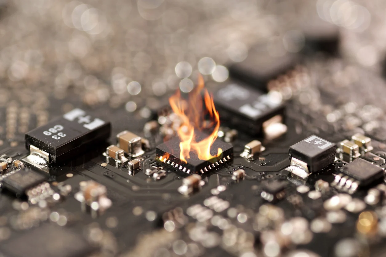
Individual components, including passive elements like capacitors and resistors, or even the microprocessor itself, are prone to failure. This can be caused by factors such as overheating, inherent manufacturing defects, or the natural process of aging. Surface-mount capacitors, for example, are a notorious source of intermittent shorts or open circuits over time. Microprocessors are also significant heat generators, and inadequate thermal management can lead to critical failures like solder joint fatigue, board delamination, or even catastrophic component burnout. Furthermore, environmental factors such as high humidity or accumulated dust can cause gradual corrosion or lead to unintended short circuits over extended periods. Occasionally, the root cause isn't hardware at all, but rather a mismatch or bug within the firmware or software that dictates the microprocessor's operation. Keeping these potential issues in mind significantly streamlines the PCB failure analysis process.
A Systematic Approach to Diagnosing Microprocessor PCB Issues
Initial Inspection and Power Verification
Embark on the troubleshooting journey with a thorough visual inspection of the PCB. Look for any overt signs of damage: burnt components, discolored (blackened) areas on the board, cracked or bulging capacitors (often indicative of failure), or visibly broken traces and solder joints, particularly in regions prone to high heat around the microprocessor. For surface-mount components, a magnifying glass or microscope is invaluable, as defects can be minute. This initial visual check can quickly reveal issues without the need for advanced diagnostic equipment.
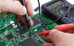
Following the visual inspection, rigorously test the power supply, as power-related problems are a leading cause of microprocessor malfunctions. Use a multimeter to verify the input voltage and the regulated outputs directly feeding the microprocessor. For example, if a microprocessor requires 1.8V for its core, confirm that the voltage at the relevant pin falls within a tight tolerance, such as ±5% (1.71V to 1.89V). Additionally, employ an oscilloscope to analyze the power delivery network for excessive ripple or noise. Ripple exceeding 50mV peak-to-peak, for instance, can cause the microprocessor to reset unexpectedly or operate erratically.
Signal Analysis and Component-Level Checks
Next, focus on signal integrity, a critical aspect of microprocessor PCBs, especially for high-speed data lines. An oscilloscope is the indispensable tool here; use it to examine clock signals and data buses for signs of overshoot, undershoot, ringing, or timing inaccuracies. A clean 25 MHz clock signal, for example, should exhibit crisp edges with rise times typically under 1 nanosecond to prevent clock jitter and ensure reliable data capture. If signal integrity issues are suspected, closely examine the PCB layout: are high-speed traces routed too close together without adequate isolation? Are proper ground planes in place? Maintaining a trace spacing of at least three times the trace width can significantly reduce crosstalk in many designs.
If both power and signal integrity appear sound, proceed to test individual components. Start with passive elements like capacitors and resistors using a multimeter or LCR meter. A shorted decoupling capacitor situated near the microprocessor's power pins, for instance, can effectively pull down the critical core voltage, preventing the chip from initializing. For the microprocessor itself, check for any signs of operational activity by verifying clock oscillations or the state of reset signals. If the chip appears non-responsive or "dead," replacement may be necessary, a task that demands precise soldering or rework skills depending on its package type.
Environmental Factors and Firmware Validation
Consider the thermal performance of the quick turn PCB. Microprocessors generate considerable heat, and insufficient thermal management can lead to premature failure. Use a thermal camera to pinpoint any localized hot spots on the board. If the microprocessor or surrounding voltage regulators exceed their safe operating temperatures (often specified as 85°C to 105°C in datasheets), improving cooling with passive heat sinks or active airflow solutions becomes imperative. Additionally, environmental conditions such as high humidity or accumulated dust can contribute to gradual corrosion or create intermittent short circuits over time.
If all hardware tests yield no conclusive fault, the issue may reside within the firmware or application software. Attempt to reload the firmware, or test the board with a previously known good version. Utilize advanced debugging tools like JTAG (Joint Test Action Group) or SWD (Serial Wire Debug) interfaces to step through the code execution. This allows you to observe whether the microprocessor is executing instructions as expected and interacting correctly with its peripherals.
Advanced Repair Techniques for Microprocessor Boards
Once the root cause of the malfunction has been pinpointed through microprocessor PCB troubleshooting, it's time to apply appropriate PCB repair techniques.
Replacing Components and Repairing Traces
For common surface-mount components like capacitors or resistors, a hot air rework station is the ideal tool for carefully desoldering and replacing the faulty part. It is crucial that the replacement component precisely matches the original specifications; substituting a 10uF capacitor with a 1uF component, for example, can severely destabilize the power delivery network. Replacing the microprocessor itself is a far more delicate operation, especially with fine-pitch or BGA (Ball Grid Array) packages, requiring a specialized rework station capable of precise temperature profiling to prevent damage to adjacent components.
Damaged traces can often be salvaged using conductive epoxy or by meticulously soldering a small jumper wire across the break. For cracked or "cold" solder joints, carefully reflow the joint with a soldering iron, adding a small amount of fresh solder and flux. Exercise extreme caution: applying excessive heat (e.g., above 300°C for more than 10 seconds) can cause irreversible damage to the PCB substrate or surrounding components.
Addressing Layout-Induced Signal Integrity Issues
If signal integrity problems are definitively traced back to suboptimal PCB layout, immediate temporary solutions might include adding termination resistors (e.g., 50-ohm resistors on high-speed lines) to mitigate reflections. However, for a robust and permanent resolution, a complete redesign of the multilayer PCB is often necessary, focusing on improved trace routing, optimized impedance control, and the implementation of robust ground and power planes.
Preventing Future Microprocessor PCB Failures Through Proactive Design
While troubleshooting and repair skills are indispensable, prevention remains the superior strategy. Integrating these practices into your design workflow can significantly reduce common PCB problems in future designs:
● Prioritize Thermal Management: Integrate effective thermal solutions from the outset, including adequate heat sinks, well-designed ventilation, and strategically placed thermal vias directly under high-power components to efficiently dissipate heat away from critical areas.
● Specify High-Quality Components: Opt for reputable brands and meticulously review datasheets to ensure that component temperature, voltage, and current ratings are appropriately matched to your application's operational demands, providing sufficient safety margins.
● Adhere to Signal Integrity Best Practices: Design high-speed traces with consistent impedance (e.g., maintaining 50 ohms characteristic impedance) and avoid sharp, 90-degree corners in routing to minimize reflections and signal degradation. Implement robust power and ground planes to provide stable references.
● Early and Iterative Testing: Develop prototypes and subject your PCBs to rigorous stress testing under conditions that accurately simulate real-world operational environments. This proactive approach allows for the early detection and rectification of potential issues before products enter mass production.
Essential Tools for Effective Microprocessor PCB Troubleshooting
Having the right diagnostic tools at your disposal simplifies the process of diagnosing microprocessor issues dramatically:
● Multimeter: The foundational tool for accurately measuring voltage levels, current draw, and verifying circuit continuity.
● Oscilloscope: An essential instrument for visualizing signal waveforms, analyzing timing relationships, detecting noise, and identifying signal integrity issues like overshoot or undershoot.
● Thermal Camera: Invaluable for quickly identifying localized hot spots on the PCB, indicating areas of excessive heat generation or poor thermal dissipation.
● Hot Air Rework Station: Critical for safely desoldering and replacing surface-mount components, especially those with multiple pins or fine pitches.
● Magnifying Tools: Aids like a loupe, stereo microscope, or digital microscope are crucial for detailed visual inspection of tiny components, solder joints, and fine traces.
● Logic Analyzer: Highly effective for debugging digital signals in complex microprocessor circuits, allowing for simultaneous observation of multiple data lines and timing analysis.
● JTAG/SWD Debugger: Essential for interacting directly with the microprocessor, allowing engineers to step through firmware, inspect registers, and set breakpoints.
Case Study: A Real-World Microprocessor Diagnostic Success
To illustrate the practical application of these concepts, consider a past project involving an embedded system powered by an ARM Cortex-M4 microprocessor. The board would power up, but consistently failed to execute its firmware. A initial visual inspection revealed no obvious physical damage. However, when I systematically checked the power supply using a multimeter, I discovered that the microprocessor’s core voltage was only 1.1V, falling short of the required 1.2V – a critical 0.1V deficit that was preventing the chip from operating correctly.
Further investigation with the multimeter allowed me to trace the voltage drop to a shorted decoupling capacitor positioned strategically near the microprocessor's power pins. After desoldering and replacing the faulty 10uF capacitor with a new one, the core voltage stabilized precisely at 1.2V, and the board immediately began functioning as intended. This experience strongly underscored the vital importance of commencing with thorough power supply checks as a foundational step in any PCB failure analysis, demonstrating how seemingly minor voltage deviations can halt an entire system.
Conclusion: Mastering Microprocessor PCB Troubleshooting for Success
Troubleshooting microprocessor PCBs, while potentially daunting, does not have to be an overwhelming endeavor. By diligently adhering to a structured and systematic approach—beginning with meticulous visual inspection, progressing through rigorous power supply testing, comprehensive signal integrity analysis, thorough component checks, and finally, applying precise repair techniques—you can confidently tackle even the most intricate issues. Whether you are confronting common PCB problems or grappling with complex microprocessor issues, the proven methods and insights detailed in this guide will empower you to efficiently diagnose and rectify malfunctions, ensuring the reliability and functionality of your electronic designs.


