Introduction
Flexible printed circuit boards (PCBs) have become essential in modern electronics, enabling innovative designs in wearables, medical devices, and compact consumer products. The ability to bend without breaking is a defining feature of these circuits, and core thickness plays a critical role in achieving this balance of flexibility and durability. For electric engineers, understanding how core thickness impacts PCB flexibility is vital for successful designs in bendable circuits. This article explores the relationship between core thickness and flexibility in flexible PCB design, alongside material selection, bending radius considerations, and manufacturing practices. By adhering to established industry standards, engineers can create reliable flexible electronics applications that meet performance and safety requirements.
What Is Flexible PCB Design and Why It Matters
Flexible PCB design involves creating circuits that can bend, fold, or conform to non-planar shapes while maintaining electrical functionality. Unlike rigid PCBs, these boards use thin, pliable substrates, allowing them to fit into tight spaces or endure repeated flexing. Core thickness, the measure of the base material layer, directly influences how much a PCB can bend without damage. For electric engineers, this is crucial in applications like wearable sensors, automotive systems, and aerospace electronics, where space constraints and dynamic movement are common.
The importance of flexible PCBs lies in their ability to reduce weight, save space, and improve reliability in harsh environments. They eliminate the need for bulky connectors and cables, streamlining assembly. However, poor design choices, especially in core thickness, can lead to mechanical failure or signal loss. Thus, mastering flexible PCB design ensures innovative products that withstand real-world stresses while meeting industry expectations.
Technical Principles of Core Thickness and PCB Flexibility
Core thickness in flexible PCBs typically ranges from a few micrometers to a fraction of a millimeter, depending on the application. Thinner cores enhance flexibility, allowing tighter bending radii, while thicker cores provide better structural support and durability. The challenge lies in balancing these factors to avoid cracking or delamination during bending.
The bending radius, defined as the minimum radius a PCB can bend without damage, is closely tied to core thickness. A thinner core reduces the bending radius, enabling sharper curves. However, excessively thin cores may compromise mechanical strength, risking tears or conductor breaks. Engineers must also consider the strain on copper traces, as excessive bending can cause fatigue over time. Industry guidelines, such as those in IPC-2223D, Sectional Design Standard for Flexible and Rigid-Flex Printed Boards, provide specific recommendations for bend radius ratios relative to board thickness, often suggesting a minimum radius of 6 to 10 times the thickness for single-layer flex circuits.
Material properties further influence flexibility. Polyimide, a common substrate for flexible PCBs, offers excellent thermal stability and pliability, supporting thin core designs. The dielectric constant and loss tangent of the material also affect signal integrity, especially in high-frequency flexible electronics applications. Standards like IPC-4204A, Flexible Metal-Clad Dielectrics for Use in Fabrication of Flexible Printed Circuitry, outline material requirements to ensure consistent performance under bending stress.
Impact of Core Thickness on Bendable Circuits
In bendable circuits, core thickness determines the mechanical limits of the design. A core that is too thick restricts flexibility, making it unsuitable for tight folds or dynamic applications. Conversely, an overly thin core may fail under minimal stress, especially if subjected to repeated flexing. Engineers must analyze the intended use case, whether static (bent once during installation) or dynamic (repeated bending), to select an appropriate thickness.
For static applications, a slightly thicker core can provide added robustness without sacrificing much flexibility. Dynamic applications, such as in wearable devices, demand thinner cores to accommodate frequent movement. IPC-2223D specifies different design rules for static and dynamic flexing, emphasizing tighter controls on bending radius and core thickness for dynamic scenarios to prevent fatigue failure.
Copper foil thickness, bonded to the core, also plays a role. Thinner foils, often rolled annealed copper, are preferred in flexible PCB design as they withstand bending better than thicker, electrodeposited copper. Standards like IPC-4562A, Metal Foil for Printed Board Applications, detail the properties of copper foils suitable for flex circuits, ensuring compatibility with thin core designs.
Best Practices for PCB Material Selection in Flexible Designs
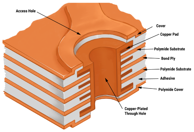
Material selection is a cornerstone of successful flexible PCB design. Polyimide films are widely used due to their high tensile strength and thermal resistance, supporting core thicknesses as low as 12.5 micrometers for ultra-flexible applications. Engineers must evaluate the glass transition temperature and moisture absorption of materials, as these affect long-term reliability under bending stress. IPC-4202B, Flexible Base Dielectrics for Use in Flexible Printed Circuitry, provides detailed specifications for selecting substrates that balance flexibility and durability.
Adhesives used in multi-layer flexible PCBs must also be flexible to prevent delamination during bending. Acrylic or epoxy-based adhesives are common, but their thickness and curing process must align with the core design to avoid adding unnecessary stiffness. Additionally, coverlay materials, which protect copper traces, should match the core’s flexibility to ensure uniform bending behavior. Referencing IPC-4203B, Cover and Bonding Material for Flexible Printed Circuitry, helps in choosing compatible materials.
Suggested Reading: Flexible PCBs: Materials, Fabrication, and Applications
Managing PCB Bending Radius for Reliable Performance
Controlling the bending radius is essential to prevent mechanical and electrical failures in flexible PCBs. A general guideline from IPC-2223D suggests a minimum bending radius of 6 times the board thickness for single-sided flex circuits, increasing to 10 times for double-sided or multi-layer designs. This ratio minimizes stress on the core and conductors, extending the lifespan of bendable circuits.
Designers should also avoid placing vias or components in bend areas, as these can create stress concentration points. Gradual bends, rather than sharp creases, distribute strain more evenly across the PCB. For dynamic applications, engineers can incorporate strain relief features, such as curved traces or teardrop-shaped pads, to reduce fatigue. Simulation tools adhering to industry standards can predict stress distribution, helping optimize the bending radius during the design phase.
Flexible Electronics Applications and Design Considerations
Flexible electronics applications span diverse industries, each with unique demands on core thickness and flexibility. In medical devices, such as implantable sensors, ultra-thin cores enable conformity to body contours while maintaining biocompatibility. Automotive systems use flexible PCBs in dashboards and sensors, requiring resistance to vibration and temperature extremes. Wearables, like smartwatches, rely on dynamic flexibility to endure constant movement.
Each application requires tailored design considerations. Medical applications often prioritize thin cores for flexibility, while automotive designs may use slightly thicker cores for durability. Engineers must also account for environmental factors, such as humidity or thermal cycling, which can affect material performance. Adhering to standards like ISO 13485:2016, Medical Devices - Quality Management Systems, ensures that flexible PCBs meet stringent safety and reliability requirements in critical applications.
Insights into Flex PCB Manufacturing Challenges
Manufacturing flexible PCBs introduces unique challenges compared to rigid boards. Core thickness variations during lamination can lead to inconsistent flexibility, affecting the final bending radius. Tight control over etching processes is necessary to avoid over-etching thin copper foils, which can weaken traces. Additionally, aligning multiple layers in multi-layer flex designs requires precision to prevent misalignment during bending.
Quality control, guided by standards like IPC-6013D, Qualification and Performance Specification for Flexible and Rigid-Flex Printed Boards, ensures that manufactured boards meet design specifications. Inspection techniques, such as automated optical inspection, help detect defects in thin cores or traces. Engineers should collaborate with manufacturing teams early in the design phase to address potential issues, ensuring that the chosen core thickness and materials are compatible with production capabilities.
Conclusion
Designing flexible PCBs that bend without breaking requires a deep understanding of core thickness, material selection, and bending radius. Electric engineers must balance flexibility with durability, tailoring designs to specific applications while adhering to industry standards like IPC-2223D and IPC-6013D. By carefully selecting materials and optimizing manufacturing processes, reliable bendable circuits can be achieved for diverse flexible electronics applications. This approach not only enhances product performance but also ensures longevity and safety in demanding environments.
FAQs
Q1: What role does core thickness play in flexible PCB design?
A1: Core thickness directly affects the flexibility and durability of a flexible PCB. Thinner cores allow for tighter bending radii, ideal for dynamic applications, while thicker cores offer better mechanical strength for static uses. Following guidelines from standards like IPC-2223D helps engineers choose the right thickness to prevent cracking or failure during bending.
Q2: How does PCB material selection impact bendable circuits?
A2: Material selection is critical for bendable circuits as it determines flexibility and thermal stability. Polyimide substrates are often chosen for their pliability and strength, supporting thin core designs. Standards like IPC-4202B provide specifications for materials, ensuring they withstand bending stress without compromising electrical performance in flexible electronics.
Q3: What is the recommended bending radius for flex PCB manufacturing?
A3: The bending radius for flex PCBs should generally be at least 6 to 10 times the board thickness, as outlined in IPC-2223D. This ratio minimizes stress on the core and traces, preventing mechanical failure. For dynamic applications, a larger radius or strain relief features can further enhance reliability during repeated flexing.
Q4: How do flexible electronics applications influence PCB design choices?
A4: Flexible electronics applications, such as wearables or medical devices, dictate specific design needs for core thickness and flexibility. Medical implants require ultra-thin cores for conformity, while automotive uses may need thicker cores for durability. Adhering to standards like ISO 13485:2016 ensures designs meet application-specific safety and performance criteria.
References
IPC-2223D — Sectional Design Standard for Flexible and Rigid-Flex Printed Boards. IPC, 2016.
IPC-4202B — Flexible Base Dielectrics for Use in Flexible Printed Circuitry. IPC, 2016.
IPC-4203B — Cover and Bonding Material for Flexible Printed Circuitry. IPC, 2018.
IPC-4204A — Flexible Metal-Clad Dielectrics for Use in Fabrication of Flexible Printed Circuitry. IPC, 2011.
IPC-4562A — Metal Foil for Printed Board Applications. IPC, 2008.
IPC-6013D — Qualification and Performance Specification for Flexible and Rigid-Flex Printed Boards. IPC, 2017.
ISO 13485:2016 — Medical Devices - Quality Management Systems. ISO, 2016.


