Introduction
The miniaturization of modern electronics has forced engineers to look beyond the constraints of traditional flat, rigid circuit boards. As devices become smaller, lighter, and more geometrically complex, the interconnect system must adapt to fit within non-standard enclosures while maintaining high reliability. This evolution has made flexible and rigid-flex circuit technologies essential components in industries ranging from aerospace to consumer electronics.
This pillar page serves as a foundational resource for understanding the ecosystem of flexible circuitry. It addresses the core engineering challenges associated with bending constraints, material selection, and complex fabrication processes. By establishing a structured approach to these dynamic interconnects, we aim to help technical decision-makers move from concept to manufacturable reality without encountering costly design iterations.
Core Concepts and Overall Framework
Before examining specific manufacturing or design nuances, it is critical to define the architecture that separates these technologies from standard rigid boards.
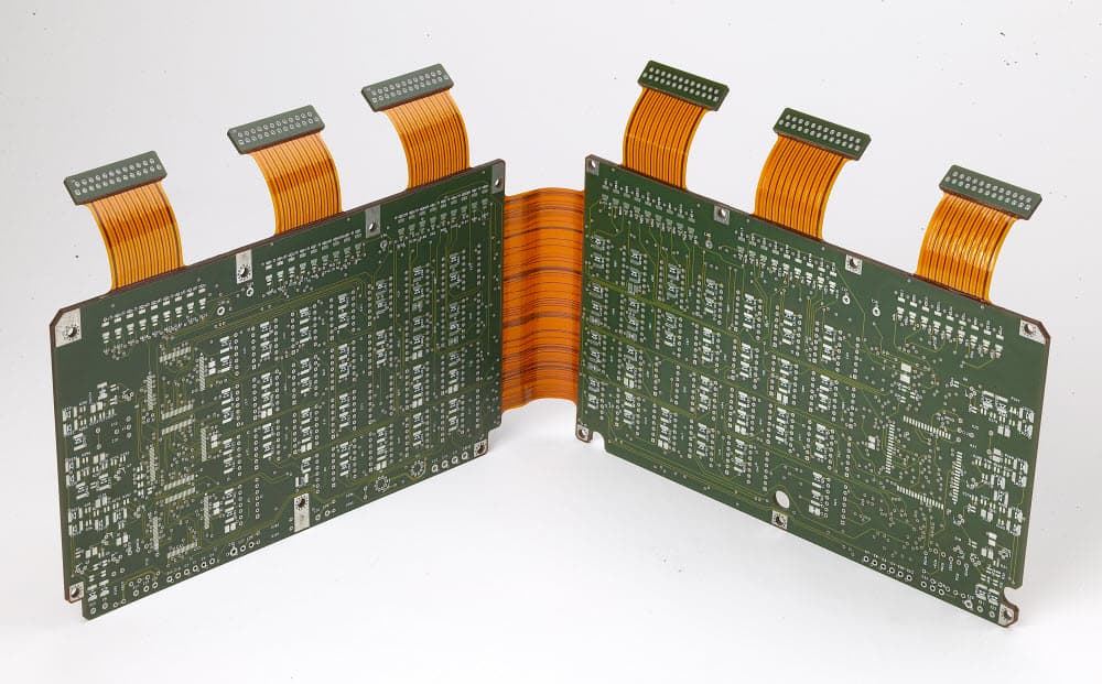
Flexible PCBs (Flex Circuits): These consist of a conductive circuit pattern on a flexible polymer film, typically with a protective coverlay. They function as connectors, wire harnesses, or fully populated circuit boards that can bend, fold, or twist.
Rigid-Flex PCBs: This hybrid technology combines the stability of rigid boards with the versatility of flex circuits. Flexible layers are laminated internally to rigid sections, allowing the board to fold into a 3D shape during assembly or flex dynamically during operation.
Key Classifications:
-
Static Flex (Flex-to-Install): The circuit bends only once during assembly to fit into the housing.
-
Dynamic Flex: The circuit bends continuously during the product's operation, such as in a printer head or a flip phone hinge.
Understanding this framework is vital because the classification dictates the material set and the design rules required for a successful build.
Fundamentals of Flexible Circuit Technology
To fully leverage the benefits of flexible electronics, one must first understand the broad scope of their fabrication and utility. This section establishes the baseline for how these circuits are constructed and where they offer the most significant advantages over traditional cabling.
The transition from bulky wire harnesses to sleek, printed flexible circuits offers immediate reductions in weight and space, but it also introduces unique fabrication variables. A comprehensive overview of flexible pcb materials, fabrication, and applications reveals that success lies in balancing mechanical flexibility with electrical performance. Unlike rigid boards that rely on fiberglass reinforcement, flex circuits utilize thin polymer films that require specialized handling throughout the production line. Engineers often utilize these boards to eliminate connectors, reduce assembly labor, and improve signal integrity by maintaining uniform impedance across the interconnect.
Critical Material Selection for Flex Layers
The physical properties of the substrate define the mechanical endurance and thermal resistance of the final product. Choosing the correct chemistry is the single most important decision in the early design phase, as it impacts everything from solderability to dynamic bend life.
While standard FR4 is the default for rigid boards, it cracks under strain, necessitating a shift toward advanced polymers designed for deflection. Deep knowledge of flexible pcb materials ensures that the chosen substrate can withstand the required number of flex cycles without work hardening the copper. Polyimide is the industry standard due to its robust thermal stability and excellent electrical properties, whereas polyester might be used for cost-sensitive, low-temperature applications. Furthermore, the selection between adhesive-based and adhesiveless laminates plays a pivotal role in reducing thickness and improving reliability in high-frequency designs.
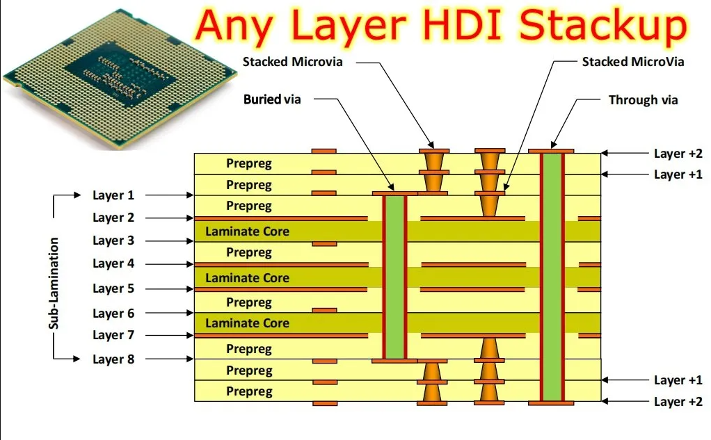
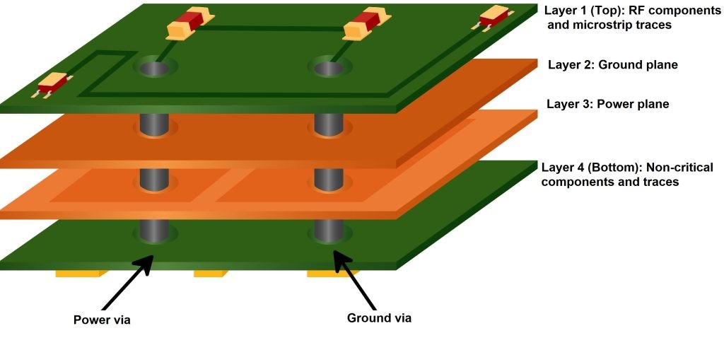
Strategic Stack-up Design for Rigid-Flex Boards
Merging rigid and flexible technologies creates a complex vertical architecture that requires meticulous planning to prevent mechanical failure. This section addresses the structural logic required to bond dissimilar materials into a single, cohesive unit.
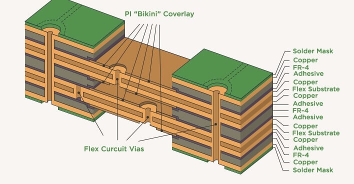
Combining the stability of hardboards with the versatility of flexible circuits requires a strategic approach to layer management and interface integrity. Implementing professional rigid-flex pcb stack-up design protocols involves placing the flexible layers in the center of the stack to minimize strain during bending. Designers must pay close attention to the transition zone where the rigid material ends and the flexible arm begins. This interface is a high-stress point where delamination often occurs if the stack-up is not balanced or if the adhesive flow is not controlled. Ensuring the neutral bend axis is positioned correctly within the stack-up is essential for maximizing the life of the connection.
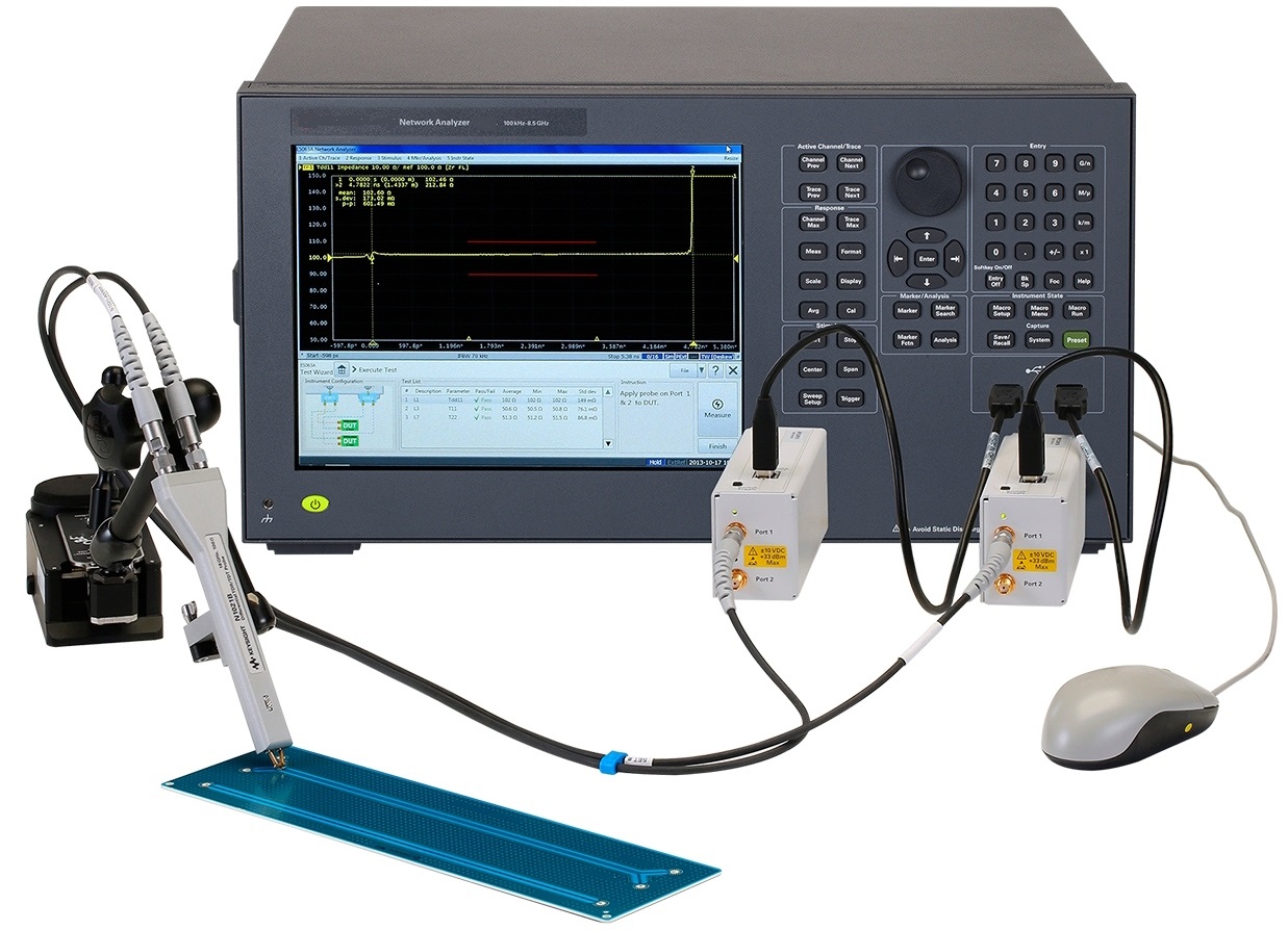
Specialized Manufacturing Equipment and Handling
The fabrication floor for flexible electronics looks vastly different from a standard rigid board shop due to the delicate nature of the materials. Processing thin, non-reinforced films requires equipment capable of managing dimensional instability and preventing physical damage.
Because flexible laminates are flimsy and prone to shrinking or stretching during thermal cycles, standard conveyor systems are often inadequate. Advanced flexible pcb manufacturing equipment utilizes sophisticated tension control systems or rigid carrier pallets to transport the substrates through etching and plating baths. Laser direct imaging is frequently employed to account for material distortion that occurs during processing. Understanding these equipment capabilities helps designers realize why certain tight tolerances or feature sizes that are standard on rigid boards may be cost-prohibitive or impossible to achieve on a flexible substrate.
Rigid-Flex PCB Applications in Medical
The ultimate test of flexible technology often lies in sectors where failure carries life-threatening consequences. The medical industry drives much of the innovation in miniaturization, demanding interconnects that are biocompatible, lightweight, and extremely reliable.
The demand for compact diagnostics and minimally invasive tools has driven rigid-flex pcb applications in medical devices to new levels of sophistication. In applications such as smart catheters, hearing aids, and implantable sensors, the circuitry must conform to organic shapes and endure the harsh environment of the human body or sterilization processes. Rigid-flex technology allows engineers to fold complex logic circuits into tiny volumes while extending flexible sensors to the precise point of measurement. This capability is revolutionizing patient care by enabling devices that are less intrusive and more capable than ever before.

Interdependence of Material and Fabrication
The relationship between raw material inputs and manufacturing outputs is far tighter in flex circuits than in rigid ones. For instance, the choice of a coverlay over a flexible soldermask is not just an aesthetic preference; it dictates the minimum bend radius and the processing steps required.
Impact on Yield:
Using an adhesiveless copper clad laminate improves flexibility and thermal performance, but it may require different chemical etching parameters than adhesive-based systems. Similarly, the decision to use "dynamic flex" materials influences the copper grain structure required, which in turn affects the plating equipment settings. A holistic view ensures that the material specified in the print can actually be processed by the fabrication machinery without excessive scrap.
Industry Considerations for Reliability and Cost
From an engineering management perspective, adopting flexible circuit technology requires a shift in how value is calculated. While the unit cost of a rigid-flex board is significantly higher than a rigid PCB and cable assembly, the total cost of ownership often tells a different story.
Reliability Factors:
Eliminating connectors removes the most common point of failure in electronic systems. In high-vibration environments, such as aerospace or industrial robotics, this integrated approach significantly improves mean time between failures (MTBF).
Cost Drivers:
The primary cost drivers in this sector are layer count and material utilization. Because flex materials are expensive, panel utilization becomes a critical design constraint. Experienced engineers will often nest flexible parts in odd shapes to maximize yield from the production panel. Balancing these cost factors against the performance requirements is the hallmark of a mature design strategy.
Conclusion
Flexible and Rigid-Flex PCBs represent a sophisticated convergence of material science, mechanical engineering, and electronic design. They are no longer just a solution for tight spaces; they are an enabling technology for the next generation of high-performance devices.
By understanding the distinct properties of flexible materials, the complexities of hybrid stack-ups, and the specialized equipment required for manufacturing, engineers can design systems that are both innovative and robust. The journey from a concept to a reliable product requires respecting the unique physical rules of these bendable substrates. As industries continue to demand smaller, lighter, and more capable electronics, the mastery of flexible circuit technology will remain a defining skill for successful hardware development.