Introduction
Thermal management in printed circuit board (PCB) design is a critical aspect for electrical engineering professionals aiming to ensure reliability and performance in electronic systems. As devices become more compact and power-dense, managing heat dissipation effectively is essential to prevent failures and extend component lifespan. Poor thermal design can lead to overheating, degraded performance, and even catastrophic failures in high-stake applications. This article explores the best practices for thermal PCB design, focusing on strategies like vias usage, component placement, PCB stackup optimization, airflow considerations, and heatsinking techniques. By adhering to these principles, engineers can mitigate thermal risks and enhance system durability. The insights provided are grounded in industry standards and practical engineering approaches, tailored for professionals seeking actionable guidance in thermal management.
Why Thermal Management Matters in PCB Design
Thermal management in PCB design directly impacts the reliability and efficiency of electronic systems. Excessive heat can cause component degradation, signal integrity issues, and mechanical stress due to thermal expansion. In high-power applications, such as power electronics or LED systems, ineffective heat dissipation often results in reduced operational life or sudden failures. For electrical engineers, understanding thermal behavior is vital to meet performance specifications and comply with safety standards. Effective thermal design not only prevents overheating but also ensures consistent operation under varying environmental conditions. By prioritizing thermal considerations during the design phase, engineers can avoid costly redesigns and improve the overall quality of the final product. This section sets the foundation for exploring specific techniques to address heat dissipation challenges.
Technical Principles of Thermal Dissipation in PCBs
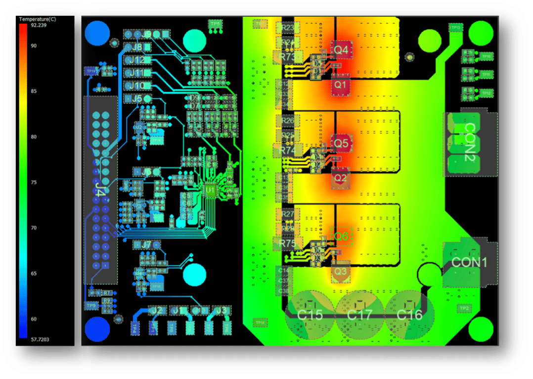
Thermal dissipation in PCBs involves the transfer of heat from heat-generating components to the surrounding environment. The primary mechanisms include conduction, convection, and radiation. Conduction occurs through the copper traces, vias, and board materials, moving heat from hot spots to cooler areas. Convection involves heat transfer via airflow over the PCB surface, while radiation plays a minor role, emitting heat as infrared energy. Key factors influencing thermal performance include the thermal conductivity of materials, the layout of heat sources, and the board's exposure to ambient conditions. High-power components, such as processors or power transistors, act as primary heat sources, necessitating strategic design to manage temperature rise. Engineers must balance these mechanisms to maintain component temperatures within safe operating limits, often guided by standards like IPC-2152 for current carrying capacity and thermal considerations.
Best Practices for Thermal PCB Design
Optimizing Component Placement for Heat Distribution
Component placement is a foundational step in thermal PCB design. Place high-power components away from sensitive parts to minimize localized heating. Position heat-generating elements near board edges or areas with better airflow to facilitate natural convection. Group components with similar thermal profiles together to avoid uneven heat distribution. Ensure adequate spacing between components to prevent heat trapping and allow efficient dissipation. For critical designs, simulate thermal profiles during the layout phase to identify potential hot spots. This practice aligns with guidelines in standards like IPC-2221B, which provides recommendations for generic PCB design, including spacing and layout for thermal considerations.
Utilizing Thermal Vias for Heat Transfer
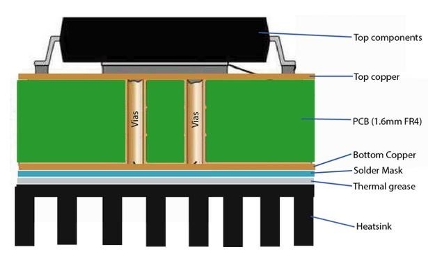
Thermal vias are small conductive pathways that transfer heat from one layer of the PCB to another, often to a ground plane or heat sink. Place vias directly beneath or near heat-generating components to create a low-resistance thermal path. Use a grid pattern of vias to maximize heat transfer while maintaining structural integrity. The diameter and number of vias should be calculated based on the expected heat load and board thickness. Filling vias with conductive material can further enhance thermal conductivity. This approach is supported by industry standards such as IPC-6012E, which specifies performance criteria for vias in rigid printed boards, ensuring reliable heat dissipation.
Related Reading: Enhancing PCB Reliability: A Guide to Thermal Vias for Heat Dissipation
Designing an Effective PCB Stackup for Thermal Performance
PCB stackup design significantly influences thermal management. Incorporate internal copper planes, such as ground or power planes, to act as heat spreaders. Thicker copper layers improve thermal conductivity, distributing heat more evenly across the board. Alternate signal and plane layers to balance thermal and electrical performance. For multilayer boards, dedicate specific layers to thermal dissipation by connecting them to external heat sinks through vias. Ensure symmetry in stackup to prevent warpage due to thermal expansion differences. Standards like IPC-2222A provide guidance on sectional design for multilayer PCBs, including considerations for thermal balance and material selection.
Enhancing Airflow Around the PCB
Airflow plays a crucial role in convective heat transfer. Design enclosures with vents or perforations to promote natural or forced convection around the PCB. Orient components and the board itself to align with airflow direction, minimizing obstructions. In systems with fans, position the PCB to receive direct airflow over high-heat areas. Avoid placing tall components in areas that block air movement to other parts. For densely populated boards, consider spacing or staggered layouts to reduce airflow resistance. This practice ensures efficient cooling, particularly in compact designs where heat buildup is a concern.
Implementing Heatsinking Solutions
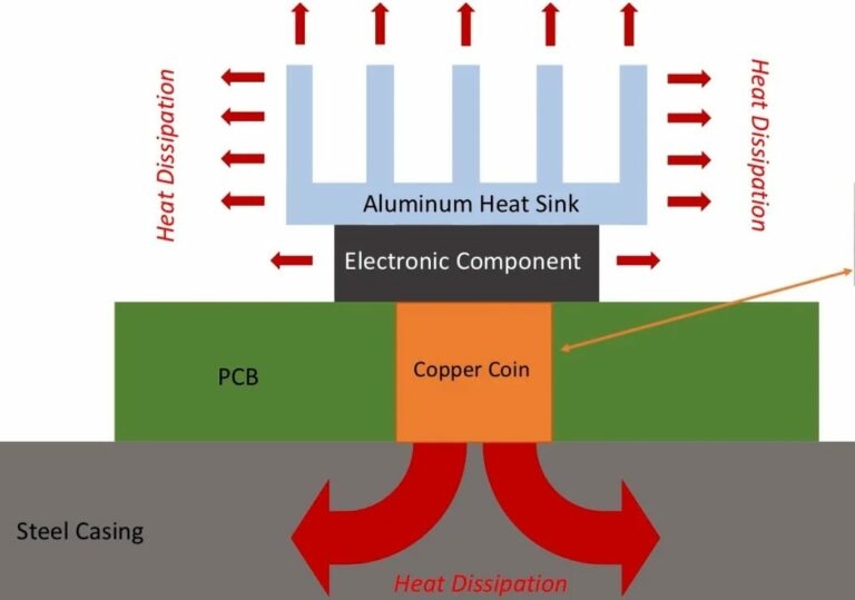
Heatsinking is a direct method to manage thermal loads in high-power applications. Attach heat sinks to components generating significant heat, ensuring proper contact through thermal interface materials. Use larger heat sinks or finned designs to increase surface area for better convection. Connect heat sinks to the PCB using thermal vias or dedicated copper areas to enhance heat transfer. In some cases, integrate the PCB itself into the heat sink structure by mounting it on a metal chassis. This approach must consider mechanical stress and thermal expansion, aligning with recommendations in standards like JEDEC J-STD-020E for component thermal stress during assembly.
Selecting Materials with High Thermal Conductivity
Material selection is vital for thermal performance. Choose substrates with high thermal conductivity, such as metal-core PCBs for extreme heat applications. Opt for copper thicknesses that support heat spreading without compromising electrical design rules. Consider dielectric materials with low thermal resistance for multilayer boards. Surface finishes should withstand thermal cycling without degrading. Adhering to material specifications in standards like IPC-A-600K ensures acceptability of printed boards under thermal stress, guiding engineers in selecting appropriate laminates and finishes for heat dissipation.
Related Reading: Thermal PCB design
Practical Insights for Thermal Design Challenges
In real-world scenarios, thermal design often faces constraints like limited board space or high component density. Engineers can address these by prioritizing critical components for thermal relief, using simulation tools to predict heat distribution before fabrication. Iterative testing under operating conditions helps validate design assumptions. For instance, in compact consumer electronics, combining thermal vias with minimal heat sinks can achieve significant cooling without increasing footprint. In industrial applications, robust airflow designs might take precedence due to harsher environments. These practical approaches, grounded in engineering experience, help balance thermal performance with other design requirements, ensuring reliability across diverse use cases.
Conclusion
Effective thermal PCB design is indispensable for ensuring the reliability and longevity of electronic systems in electrical engineering. By implementing best practices such as strategic component placement, thermal vias integration, optimized PCB stackup, enhanced airflow, and robust heatsinking, engineers can significantly reduce thermal risks. These techniques, supported by adherence to recognized industry standards, provide a structured approach to managing heat dissipation. As electronic devices continue to evolve with higher power demands, prioritizing thermal management early in the design process becomes even more critical. Applying these principles allows for safer, more efficient designs tailored to specific application needs.
FAQs
Q1: How do thermal vias improve PCB heat dissipation?
A1: Thermal vias create a conductive path for heat to travel from components to other layers or heat sinks on the PCB. By placing vias near heat sources, engineers can reduce thermal resistance and prevent hot spots. Their effectiveness depends on quantity, placement, and material conductivity. This approach is widely used in high-power designs to maintain safe operating temperatures.
Q2: What role does component placement play in thermal PCB design?
A2: Component placement is crucial for even heat distribution on a PCB. Positioning high-power components near edges or airflow paths aids natural cooling. Spacing heat-sensitive parts away from hot zones prevents damage. Proper layout reduces thermal stress and enhances overall system reliability in electrical engineering projects.
Q3: Why is PCB stackup important for thermal management?
A3: PCB stackup influences how heat spreads across layers. Incorporating copper planes as heat spreaders in the stackup design helps distribute thermal energy evenly. A balanced stackup also minimizes warpage from thermal expansion. Following industry guidelines ensures thermal and electrical performance are optimized for engineering applications.
Q4: How does airflow impact thermal performance in PCB systems?
A4: Airflow facilitates convective cooling by removing heat from the PCB surface. Designing enclosures with vents or using fans directs air over critical areas, reducing temperature buildup. Aligning components with airflow paths minimizes resistance. This is essential for maintaining thermal stability in compact or high-density electrical designs.
References
IPC-6012E — Qualification and Performance Specification for Rigid Printed Boards. IPC, 2020.
IPC-A-600K — Acceptability of Printed Boards. IPC, 2020.
IPC-2221B — Generic Standard on Printed Board Design. IPC, 2012.
IPC-2222A — Sectional Design Standard for Rigid Organic Printed Boards. IPC, 2010.
JEDEC J-STD-020E — Moisture/Reflow Sensitivity Classification for Nonhermetic Surface Mount Devices. JEDEC, 2014.


