Introduction
Flexible printed circuit boards (PCBs) are essential in modern electronics, enabling compact, lightweight, and adaptable designs for applications in medical devices, wearables, automotive systems, and aerospace technology. Unlike rigid PCBs, flexible circuits require specialized manufacturing equipment to handle their thin, bendable substrates without causing damage or compromising performance. This article explores the critical role of flexible PCB assembly equipment, focusing on handling equipment for flex PCBs, laser cutting for flexible circuits, adhesive bonding for flexible PCBs, and testing flexible circuit boards. Aimed at electrical engineers, this content provides technical insights into the tools and processes that ensure precision and reliability in flex PCB production, aligning with recognized industry standards to maintain quality and consistency.
What Are Flexible PCBs and Why Do They Matter
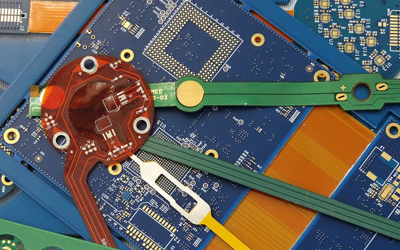
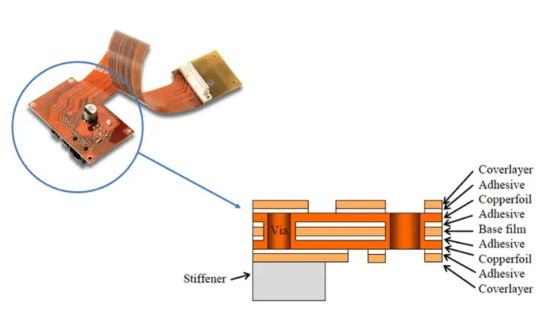
Flexible PCBs are circuits built on pliable materials like polyimide or polyester, allowing them to bend, fold, or conform to unique shapes. Their ability to reduce space and weight makes them indispensable in devices where traditional rigid boards are impractical. For instance, in wearable technology, flex PCBs enable seamless integration into curved or moving components. The manufacturing of these boards, however, presents unique challenges due to their delicate nature. Equipment must accommodate thin substrates, often less than 0.1 mm thick, while maintaining precision during cutting, bonding, and testing. As demand for smaller, more versatile electronics grows, mastering the intricate flexible PCB manufacturing process becomes crucial for engineers to meet performance and durability expectations in high-stakes applications.
Technical Principles of Handling Thin and Bendable Substrates
Handling thin and bendable substrates requires a deep understanding of material properties and mechanical stresses. Flexible PCB substrates are prone to tearing, wrinkling, or stretching if not managed properly during manufacturing. Equipment designed for flex PCBs must minimize contact pressure and prevent distortion while ensuring accurate positioning. Vacuum-based handling systems are often employed to gently secure substrates without applying excessive force. Additionally, automated transport mechanisms with adjustable tension control help maintain substrate integrity during transfer between process stages. Environmental factors, such as humidity and temperature, also play a role, as they can affect material behavior. Equipment must therefore operate within controlled settings to avoid adverse impacts on the substrate's dimensional stability.
Beyond physical handling, alignment precision is critical. Flexible materials can shift or deform under minimal stress, leading to misalignment during layer stacking or component placement. Advanced vision systems integrated into flexible PCB assembly use high-resolution imaging to detect and correct positional deviations in real time. These systems ensure that each layer aligns perfectly, which is vital for multi-layer flex designs where even slight offsets can cause electrical failures. Engineers must prioritize equipment with such capabilities to achieve consistent results, especially when working with intricate patterns or high-density interconnects.
Key Flexible PCB Manufacturing Processes
The fabrication of flexible PCBs involves a series of highly specialized steps, each tailored to the unique properties of thin, pliable substrates.
Imaging and Etching for Circuit Definition
Imaging and etching are foundational steps in defining the circuit patterns on flexible substrates. Initially, a photoresist layer is applied and selectively exposed to UV light, transferring the circuit design with high precision. This photolithography process is critical for achieving the fine lines and spaces required in compact flexible designs. Subsequently, chemical etching removes the unexposed copper, leaving behind the desired circuitry. For delicate flexible PCB substrates, specialized methods like plasma etching are increasingly employed. These gentle etching techniques minimize thermal and mechanical stress, crucial for maintaining the integrity of thin films and achieving precise pattern definitions without damaging the base material. Accuracy in this stage directly impacts the electrical performance and reliability of the final flexible PCB.
Drilling Precision for Interconnections
Drilling is necessary for creating vias and through-holes for interconnections and component mounting. While mechanical drilling can be used, laser drilling is often preferred for flexible circuits due to its ability to create smaller, cleaner holes with minimal stress on the delicate flexible PCB materials. High-speed laser systems can precisely ablate material, reducing the risk of tearing or delamination common with conventional drills. This precision is vital for high-density interconnect (HDI) designs and ensuring robust connections across different layers of the flexible circuit board. The choice of drilling method also influences the overall yield and reliability of flexible PCB manufacturing.
Lamination for Multi-Layer Flex Structures
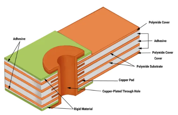
Lamination is a critical process for multi-layer flexible PCBs, where multiple circuit layers are bonded together. This involves precise alignment of etched with dielectric films and prepregs, followed by controlled application of heat and pressure. The choice of flexible PCB materials, particularly the adhesive system, is paramount to ensure strong bonds while retaining flexibility. Vacuum lamination is commonly used to prevent air entrapment, which could lead to delamination or voids. This step significantly impacts the final thickness and overall mechanical integrity of the flexible circuit, ensuring it can withstand dynamic bending without compromising electrical performance.
Laser Cutting for Flexible Circuits: Precision and Efficiency
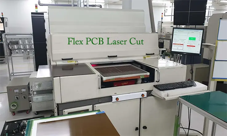
Laser cutting for flexible circuits offers unmatched precision when shaping thin substrates or creating intricate cutouts. Unlike mechanical cutting methods, lasers produce clean edges without physical contact, reducing the risk of material damage or burr formation. This technology is particularly effective for polyimide-based flex PCBs, where precise vias or outlines are needed. Laser systems typically use focused beams with adjustable power settings to control depth and avoid burning through delicate layers. Pulse duration and wavelength are tailored to the substrate material, ensuring optimal results without thermal stress.
The process also supports high-speed production, as laser cutting equipment can be programmed for complex patterns via computer-aided design files. This eliminates the need for custom dies or tooling, saving time in prototyping and small-batch runs. However, engineers must consider heat-affected zones, as excessive thermal energy can alter material properties near the cut edge. Modern laser cutting systems mitigate this by incorporating cooling mechanisms or short-pulse technologies. Adhering to guidelines in standards like IPC-2223, which addresses design and fabrication of flexible circuits, helps ensure that laser-cut features meet performance criteria.
Adhesive Bonding for Flexible PCBs: Ensuring Durability
Adhesive bonding for flexible PCBs is a critical step in assembling multi-layer designs or attaching coverlays and stiffeners. This process involves applying specialized adhesives that bond layers while maintaining flexibility and electrical insulation. Pressure-sensitive adhesives and thermally activated films are commonly used, selected based on the substrate and application requirements. The bonding equipment must apply uniform pressure and heat to activate the adhesive without deforming the thin material. Automated lamination systems with precise temperature and pressure controls are ideal for this task, ensuring consistent adhesion across the board.
A key challenge in adhesive bonding is avoiding air entrapment or delamination, which can compromise structural integrity. Equipment with vacuum lamination capabilities helps eliminate bubbles by removing air during the process. Additionally, alignment fixtures ensure that layers bond in the correct position, preventing shifts that could disrupt circuit functionality. Standards such as IPC-4203B-2018, which specifies requirements for cover and bonding materials in flexible circuits, provide detailed criteria for selecting adhesives and verifying bond strength. Engineers must align equipment settings with these guidelines to achieve reliable, long-lasting bonds.
Surface Finishing for Reliability and Solderability
Once the circuit patterns are defined and layers laminated, a surface finish is applied to the exposed copper pads. This crucial step protects the copper from oxidation and prepares the pads for optimal soldering. Common surface finish options for flexible PCBs include Electroless Nickel Immersion Gold (ENIG), Organic Solderability Preservative (OSP), and Immersion Silver. The selection depends on factors like solderability, shelf life, cost, and environmental considerations. For instance, ENIG offers excellent flatness and shelf life, crucial for fine-pitch components, while OSP is a more cost-effective and environmentally friendly option for flexible PCB applications. The integrity of the copper traces beneath the finish is vital for optimal performance and reliability during assembly and in the final application.
Testing Flexible Circuit Boards: Quality and Reliability
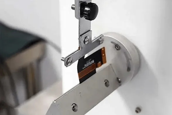
Testing flexible circuit boards is essential to validate their electrical performance and mechanical durability under real-world conditions. Unlike rigid boards, flex PCBs must withstand repeated bending or folding without failure, making dynamic testing a priority. Equipment for testing includes bending testers that simulate cyclic flexing to assess fatigue resistance. Electrical testing systems, such as flying probe testers, verify continuity, insulation resistance, and signal integrity across the circuit. These testers are designed to accommodate the non-rigid nature of flex PCBs, often using soft contact probes to avoid damaging the substrate.
Environmental testing is equally important, as flex PCBs may be exposed to varying temperatures, humidity, or vibrations in applications like automotive or aerospace. Chambers that replicate these conditions help evaluate material stability and adhesion under stress. Standards like IPC-6013, which outlines qualification and performance requirements for flexible printed boards, provide benchmarks for acceptable test outcomes. Additionally, IPC-9204 offers guidelines for strain and flexibility testing, ensuring that equipment settings and test protocols align with industry expectations. Engineers must integrate these standards into their testing workflows to confirm product reliability.
Best Practices for Flexible PCB Manufacturing Equipment
To optimize the use of flexible PCB assembly equipment, engineers should follow several best practices. First, regular calibration of handling equipment for flex PCBs is necessary to maintain precision in positioning and tension control. Misaligned or poorly maintained systems can introduce defects, especially in high-density designs. Second, when using laser cutting for flexible circuits, always validate beam settings with test runs on scrap material to prevent overcutting or thermal damage. Monitoring equipment logs can also help identify patterns of wear or inconsistency.
For adhesive bonding for flexible PCBs, ensure that lamination equipment operates within the temperature and pressure ranges specified by material standards like IPC-4203B-2018. Cleanliness is paramount, as contaminants can weaken bonds or cause defects. Finally, when testing flexible circuit boards, combine electrical and mechanical tests to gain a comprehensive view of performance. Documenting test conditions and results, as per IPC-6013 guidelines, supports traceability and continuous improvement. By adhering to these practices, engineers can maximize equipment effectiveness and produce high-quality flex PCBs.
Insight: Overcoming Common Challenges in Flex PCB Manufacturing
One frequent challenge in flex PCB manufacturing is managing substrate warpage during handling or processing. Thin materials can deform under uneven pressure or thermal gradients, leading to misalignment or assembly failures. Engineers can address this by using handling equipment for flex PCBs with adjustable support frames that distribute stress evenly. Additionally, during laser cutting for flexible circuits, warpage near cut edges may occur if cooling is inadequate. Incorporating air or liquid cooling systems into the cutting process can minimize this issue.
Another concern is ensuring uniform adhesive application during bonding. Inconsistent adhesive thickness can lead to weak spots or delamination over time. Using automated dispensing systems with precise flow control helps achieve even coverage. Finally, testing flexible circuit boards often reveals hidden defects like micro-cracks after repeated bending. Employing high-resolution imaging alongside standard electrical tests can detect such issues early. These strategies, grounded in practical experience, help engineers navigate the complexities of flex PCB production with confidence.
Conclusion
Flexible PCB manufacturing demands specialized equipment to handle the unique challenges of thin, bendable substrates. From vacuum-based handling systems to precision laser cutting for flexible circuits, each piece of equipment plays a vital role in ensuring quality and reliability. Adhesive bonding for flexible PCBs and testing flexible circuit boards further contribute to creating durable, high-performing products. By understanding the technical principles behind these processes and adhering to industry standards like IPC-6013 and IPC-4203B-2018, engineers can optimize their workflows and overcome common obstacles. As technology advances, staying informed about equipment capabilities and best practices remains essential for success in this dynamic field.
FAQs
Q1: What key features should handling equipment for flex PCBs have?
A1: Handling equipment for flex PCBs must prioritize gentle contact to prevent substrate damage. Features like vacuum-based gripping, adjustable tension control, and precise alignment systems are essential. These ensure thin materials remain intact during transfer and processing. Environmental controls for temperature and humidity also help maintain material stability, aligning with standards like IPC-6013 for flexible board performance.
Q2: How does laser cutting for flexible circuits improve manufacturing precision?
A2: Laser cutting for flexible circuits enhances precision by using focused beams to create clean, contactless cuts. This method avoids mechanical stress on thin substrates, reducing damage risks. Programmable patterns allow intricate designs without custom tooling. Following guidelines in IPC-2223 ensures cut features meet design specs, making it ideal for vias and outlines in flex PCBs.
Q3: What challenges arise during adhesive bonding for flexible PCBs?
A3: Adhesive bonding for flexible PCBs faces challenges like air entrapment and delamination, which weaken bonds. Uneven pressure or heat can also deform substrates. Using vacuum lamination equipment and precise controls mitigates these issues. Adhering to IPC-4203B-2018 for bonding materials ensures compatibility and durability, critical for multi-layer flex designs in demanding applications.
Q4: Why is testing flexible circuit boards critical for reliability?
A4: Testing flexible circuit boards verifies both electrical performance and mechanical endurance under bending or environmental stress. It identifies defects like micro-cracks or insulation failures that could cause issues in use. Standards like IPC-9204 guide strain and flexibility tests, ensuring consistent results. Thorough testing is vital for applications in automotive or medical fields where reliability is non-negotiable.
References
IPC-6013 — Qualification and Performance Specification for Flexible Printed Boards. IPC.
IPC-2223 — Sectional Design Standard for Flexible/Rigid-Flexible Printed Boards. IPC.
IPC-4203B-2018 — Cover and Bonding Material for Flexible Printed Circuitry. IPC, 2018.
IPC-9204 — Guideline on Flexibility and Stretchability Testing for Printed Electronics. IPC.