Introduction
Hello, PCB enthusiasts and engineers. If you've ever wrestled with signal integrity issues in a high-frequency design, you know how crucial the right laminate can be. Rogers materials have been the gold standard for RF and microwave applications for decades, offering low-loss performance that standard materials simply can't match.
In the era of 5G, autonomous driving, and satellite communications, the "standard" FR-4 substrate often hits a performance ceiling. As a manufacturing consultant who's guided dozens of fabs through material transitions, I've seen firsthand how picking the wrong Rogers grade can inflate insertion loss or cause thermal mismatches in multilayer stacks.
This comprehensive guide breaks down the Rogers PCB material selection process, focusing on staples like the RO4000 series, RO3000 series, and RT/duroid laminates. We will explore the critical intersection of material science and engineering, helping you master Rogers PCB Design, optimize your workflow for Rogers PCB Manufacturing, and select the perfect substrate for every high-stakes Rogers PCB Application.
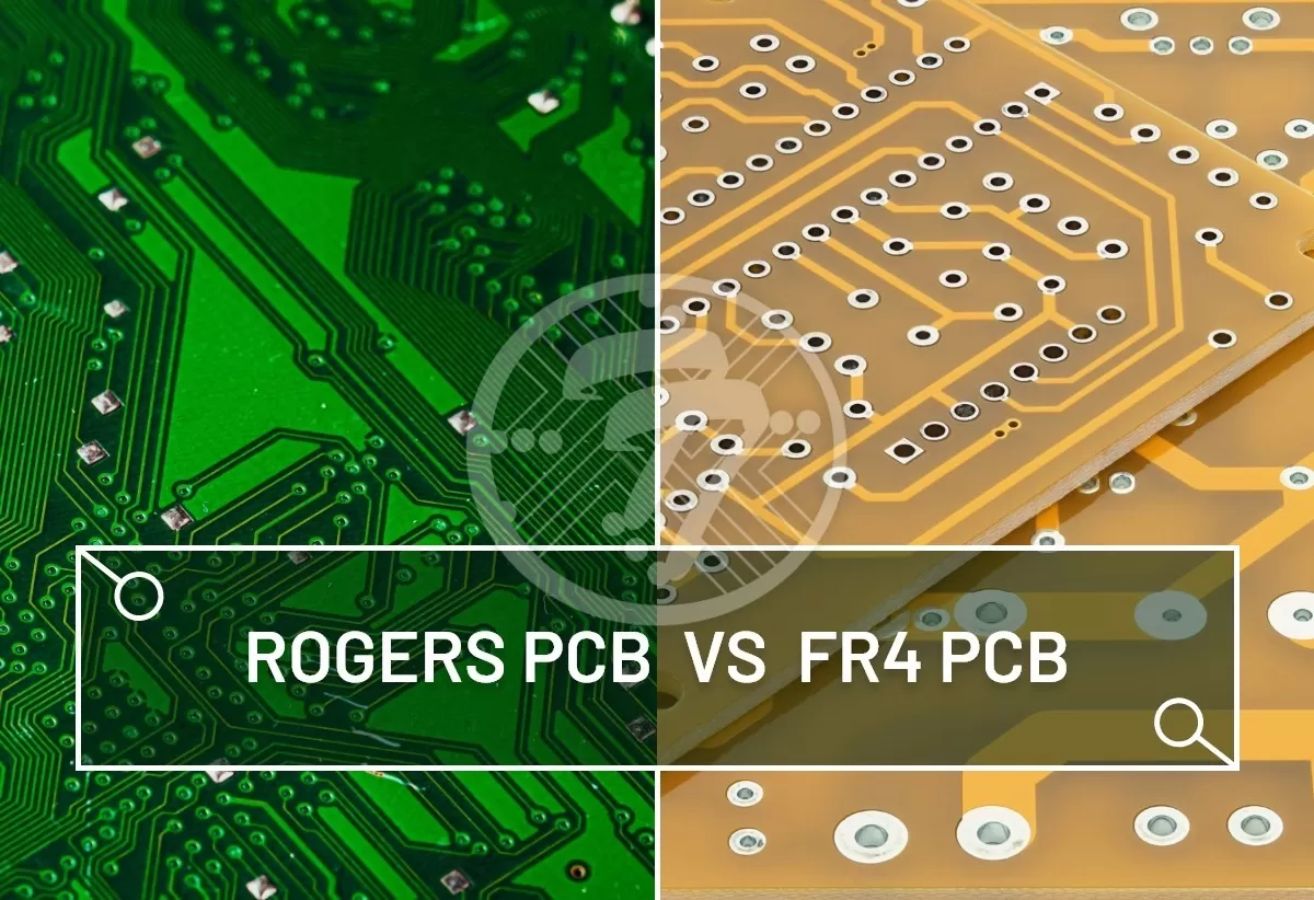
Why Rogers? Beyond the Limits of FR-4
While FR-4 is the "bread and butter" of the electronics world, it is fundamentally limited by its dissipation factor (Df) and dielectric constant (Dk) stability. Rogers materials are specialized high-performance laminates designed for high-frequency PCB applications where signals operate at GHz speeds.
Key Performance Differentiators
Unlike standard epoxy-based substrates, Rogers utilizes ceramic-filled PTFE (Polytetrafluoroethylene) or hydrocarbon composites. This results in:
-
Minimal Signal Attenuation: Crucial for maintaining signal strength over long traces.
-
Superior Phase Stability: Essential for phased-array antennas and radar.
-
Tight Dielectric Tolerances: Ensures impedance control is predictable and repeatable.
Table 1: Rogers vs. Standard FR-4 Comparison
| Property | Standard FR-4 | Rogers 4350B | Rogers 3003 |
| Dielectric Constant (Dk) | 4.2 - 4.8 | 3.48 ± 0.05 | 3.00 ± 0.04 |
| Dissipation Factor (Df) | 0.015 - 0.020 | 0.0037 | 0.0013 |
| Thermal Conductivity | 0.25 W/m/K | 0.62 W/m/K | 0.50 W/m/K |
| Moisture Absorption | 0.15% - 0.25% | 0.06% | 0.04% |
Mastering Rogers PCB Design: Principles of High-Frequency Engineering
Choosing a material is only half the battle; the other half is implementing it correctly in your layout. Rogers PCB Design requires a shift in mindset from traditional low-speed digital design.
Impedance Control and Stackup Strategy
In high-frequency circuits, every millimeter of copper acts as an antenna or a transmission line. To ensure maximum power transfer, designers must focus on:
-
Dk Stability: Rogers materials like the RO3000 series offer an incredibly stable Dk across temperature fluctuations, which is vital for outdoor telecommunications equipment.
-
Copper Surface Roughness: At frequencies above 10 GHz, "skin effect" causes signals to travel on the surface of the copper. Rough copper increases resistive loss. Rogers offers "LoPro" (low profile) copper options to mitigate this.
-
Hybrid Stackups: To balance cost and performance, many engineers use a hybrid approach—placing Rogers on the outer signal layers and using standard FR-4 for internal ground/power planes.
Deep Dive into Rogers Material Series
The RO4000 Series: The Versatile Workhorse
The RO4000 series is the most popular choice for commercial RF projects. Because it is a hydrocarbon/ceramic laminate (not PTFE), it processes similarly to FR-4.
-
RO4350B: The industry standard for power amplifiers and base station antennas.
-
RO4003C: Ideal for applications needing slightly higher performance than 4350B but maintaining ease of fabrication.
-
RO4835: Features added antioxidants to resist oxidation-related performance degradation over time.
The RO3000 Series: The Precision Specialist
These are PTFE-based materials filled with ceramic. They are engineered for consistent electrical properties across a wide temperature range.
-
RO3003: Widely used in 77 GHz automotive radar sensors due to its extremely low loss and Dk stability.
-
RO3010: A higher Dk option (10.2) that allows for circuit miniaturization.
RT/duroid: The High-Frequency Elite
Reserved for the most demanding aerospace and defense applications. The RT/duroid 5880, for instance, has a Df of 0.0009 at 10 GHz, making it one of the lowest-loss materials available. It is the go-to for millimeter-wave (mmWave) applications reaching 77GHz to 100GHz.
Table 2: Selecting Series Based on Frequency
| Frequency Range | Recommended Rogers Series | Typical Application |
| 1 GHz - 15 GHz | RO4000 Series | WiFi, IoT, Cellular Boosters |
| 15 GHz - 40 GHz | RO3000 Series | 5G Small Cells, Satellite Links |
| 40 GHz - 100 GHz | RT/duroid | Automotive Radar, EW Systems |
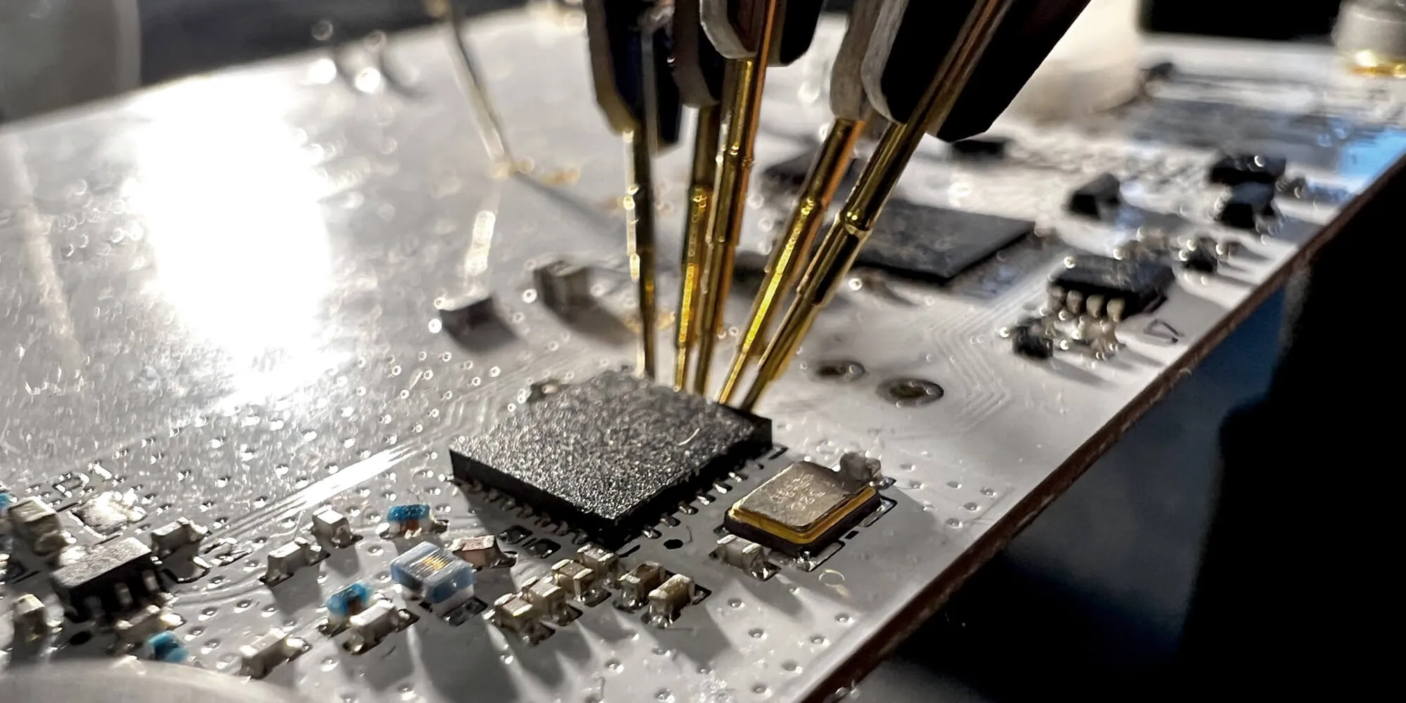
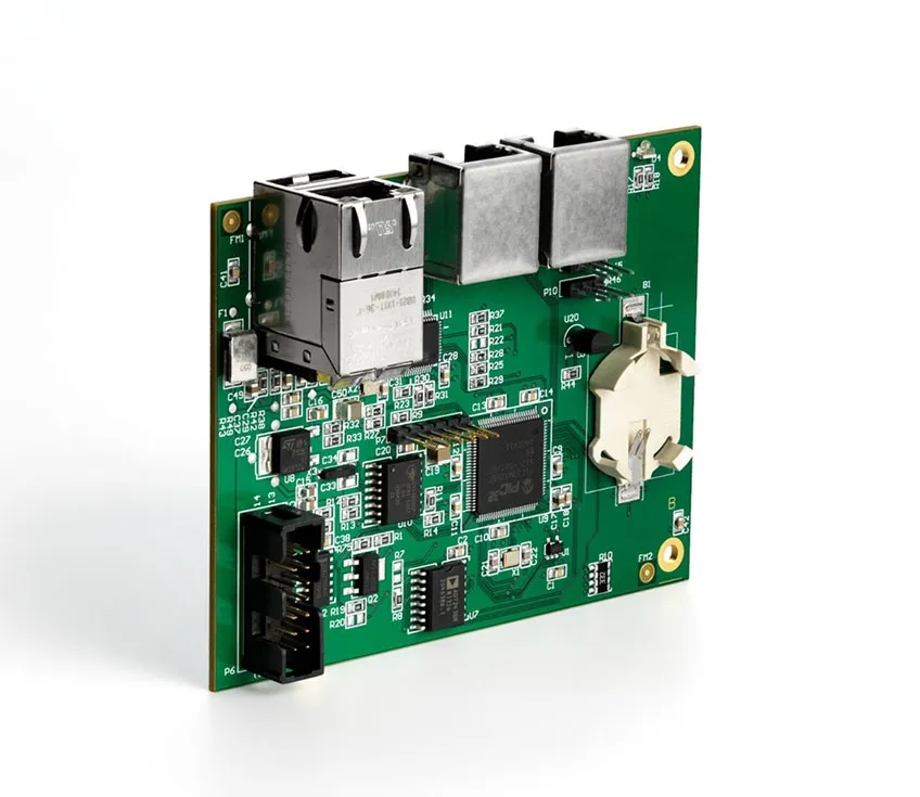
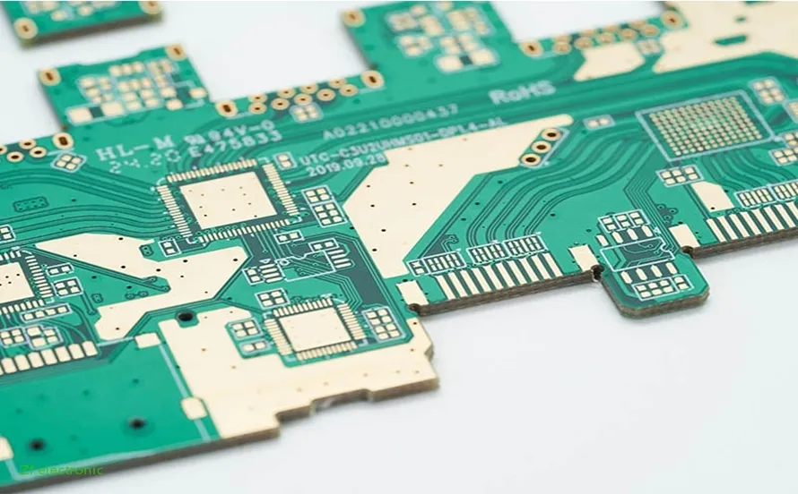
Overcoming Challenges in Rogers PCB Manufacturing
Fabricating boards with these advanced materials isn't as simple as running them through a standard production line. Successful Rogers PCB Manufacturing involves specialized chemistry and mechanical processes.
Fabrication Hurdles
-
Softness of PTFE: Materials like the RO3000 series are much softer than FR-4. If handled improperly during lamination, they can stretch or warp, leading to layer registration issues.
-
Plasma Desmear: Standard chemical desmear often fails to clean drill holes in PTFE-based substrates. Manufacturing partners must use plasma etching to ensure the copper plating bonds correctly to the hole wall.
-
Drilling Parameters: The ceramic filler in Rogers materials is highly abrasive. Specialized carbide drill bits and optimized feed/speed rates are required to prevent bit breakage and ensure clean hole walls.
Strategic Rogers PCB Application: From 5G to Space
The decision to use Rogers is usually driven by the specific Rogers PCB Application requirements.
5G Infrastructure and Telecommunications
5G NR (New Radio) utilizes higher frequency bands (FR2) that demand low-loss materials. Rogers RO4730G3 laminates are specifically designed to minimize Passive Intermodulation (PIM), which is critical for maintaining clear communication in dense urban environments.
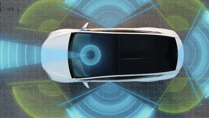
Automotive Safety and Autonomous Driving
Modern cars are essentially "computers on wheels." They rely on 77 GHz radar for adaptive cruise control and collision avoidance. The RO3003 series is the industry benchmark here because its Dk remains stable even when the car transitions from a freezing morning to a hot afternoon.
Aerospace and aviation
In avionics and satellite systems, weight and thermal management are as important as RF performance. RT/duroid materials offer low outgassing and exceptional thermal stability, ensuring the electronics don't fail in the vacuum of space or the extreme heat of a jet engine compartment.
Practical Best Practices for Engineers
To ensure a successful build, follow these strategic selection steps:
-
Define Your Power Budget: For high-power designs, focus on thermal conductivity. RO4350B (0.62 W/m/K) handles heat much better than standard PTFE materials.
-
Evaluate Environmental Conditions: If the board will operate in a humid environment, prioritize materials with low moisture absorption (like the RO3000 series) to prevent Dk shifts.
-
Consult Your Fab Early: Before finalizing your Rogers PCB Design, talk to your manufacturer. They can tell you which thicknesses they stock, which can significantly reduce lead times and costs.
Common Defects and Troubleshooting
Even with the best materials, things can go wrong. Understanding these issues early can prevent costly rework.
-
Copper Peel Strength: Certain Rogers materials have lower peel strength than FR-4. Over-etching or multiple reflow cycles can lead to pad lifting.
-
Dimensional Instability: As mentioned, PTFE is prone to "creeping." Designers should include larger annular rings to compensate for potential registration shifts.
-
Drilling Smear: If you see poor plating in the holes, it’s likely due to resin smear. This is a sign that the Rogers PCB Manufacturing process needs to adjust its plasma desmear cycle.
Future Trends in Rogers PCB Technology
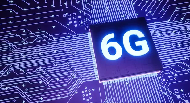
The trajectory of high-speed electronics is rapidly moving toward 6G and sub-terahertz frequencies, where signal integrity becomes exponentially harder to maintain. Future Rogers PCB Design will increasingly rely on next-generation laminates that offer near-zero dissipation factors and atomically smooth copper foils to combat the skin effect at frequencies exceeding 100 GHz. As mmWave technology expands from 77GHz automotive radar to advanced satellite sensing, we expect a surge in specialized Rogers PCB Application cases requiring ultra-stable dielectric constants across extreme temperature swings. These advancements will push the limits of material science, forcing engineers to adopt sophisticated simulation tools to predict performance before the first prototype is even built.
Furthermore, the explosion of AI-driven edge computing and the push for "green" electronics are reshaping the landscape of Rogers PCB Manufacturing. Future fabrication processes will focus on ultra-thin, high-density interconnect (HDI) structures that integrate Rogers materials with advanced thermal management solutions to dissipate heat from high-performance AI processors. We are also seeing a shift toward halogen-free, recyclable hydrocarbon laminates that maintain high-frequency performance while meeting stricter global environmental regulations. This dual focus on miniaturization and sustainability ensures that Rogers substrates will remain the backbone of global communication infrastructure, enabling smarter, faster, and more eco-friendly technology solutions for the next decade.
Conclusion
Selecting the right Rogers material is a balancing act between frequency requirements, thermal management, and budget. By understanding the unique properties of the RO4000, RO3000, and RT/duroid series, you can push the boundaries of what's possible in high-speed electronics.
Whether you are in the initial stages of Rogers PCB Design, preparing for a complex Rogers PCB Manufacturing run, or targeting a specific high-performance Rogers PCB Application, the choice of substrate will be the foundation of your success. Don't settle for "good enough"—choose the material that matches the precision of your engineering.
FAQs
Q1: Can I process Rogers 4003C like a standard FR-4 board?
A1: Mostly, yes. The RO4000 series is "FR-4 friendly," meaning it doesn't require specialized plasma desmear. However, it is more abrasive, so your manufacturer will still need to adjust drill life expectations and speeds to ensure quality.
Q2: How do Rogers materials improve 5G PCB design in wireless infrastructure?
A2: In 5G PCB design, Rogers materials offer thermal stability and low moisture uptake, preventing detuning in outdoor deployments. Engineers can achieve tighter tolerances for trace routing and vias, enhancing MIMO performance. Hybrid stackups optimize cost while prioritizing RF paths for low-loss signal transmission.
Q3: Why choose Rogers for telecom PCB in 5G base stations?
A3: Telecom PCBs using Rogers materials excel in power handling and efficiency for continuous operation. Low dissipation ensures high data throughput with reduced heat generation. Mechanical reliability suits harsh environments and aligns with industry qualification standards for high-reliability applications.
Q4: How does temperature affect Rogers PCB performance?
A4: Unlike FR-4, which can see significant changes in its dielectric constant as temperature rises, Rogers materials (especially the RO3000 series) are designed for a low Temperature Coefficient of Dielectric Constant (TCDk). This ensures that your filters and antennas stay tuned regardless of environmental heat.